
Setup and hold violations are the most common timing problems in digital design, and fixing them is a daily task for physical design and STA engineers. A design that violates setup cannot run at its target frequency; a design that violates hold fails at any frequency. In this tutorial we explain setup and hold time, how setup and hold slack are calculated with worked numeric examples, why violations happen, and how to fix setup and hold violations at each stage of the physical design flow.
What are Setup and Hold Time?
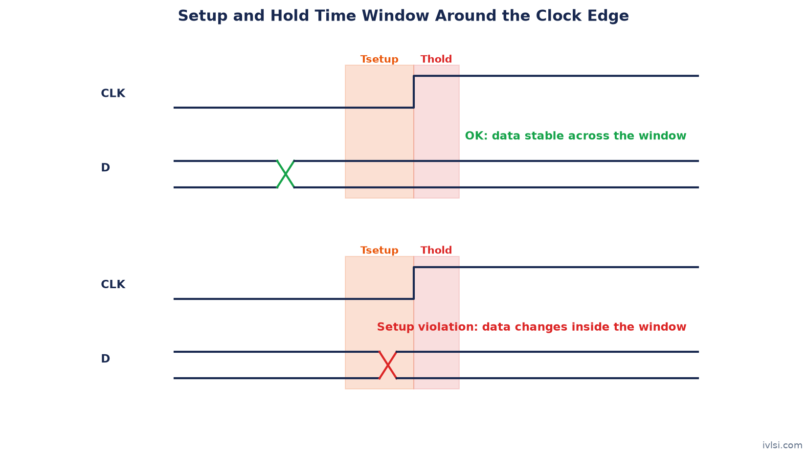
A flip-flop samples its D input at the active clock edge. To sample reliably, the data must be stable for a short window around that edge:
- Setup time (Tsetup) – the minimum time the data must be stable before the active clock edge.
- Hold time (Thold) – the minimum time the data must remain stable after the active clock edge.
Both values come from the Liberty (.lib) library of the flip-flop and depend on the data and clock transition times and the PVT corner. If data changes inside this window, the flip-flop may capture the wrong value or go metastable (its output takes an unpredictable time to settle).
Setup and Hold Violation: Definitions
- Setup violation – data arrives at the capture flop too late, after (next capture edge − setup time). It is a max-delay problem.
- Hold violation – new data arrives too early and overwrites the data that should be captured on the same edge, before (capture edge + hold time). It is a min-delay problem.
Setup Check: Equation
Consider a reg2reg path: launch flop FF1 → combinational logic → capture flop FF2, both on the same clock. Data launched at edge 0 must be captured at the next edge (one clock period later).
Data Arrival Time (DAT)  = Launch clock latency (late) + Tck2q (max) + Tcomb (max)
Data Required Time (DRT) = Tperiod + Capture clock latency (early) - Tsetup - Tuncertainty (+ CRPR)

Setup Slack = DRT - DAT
Slack ≥ 0 means no violation; slack < 0 means a setup violation. These are the same equations used in Performance (Timing) analysis during implementation.
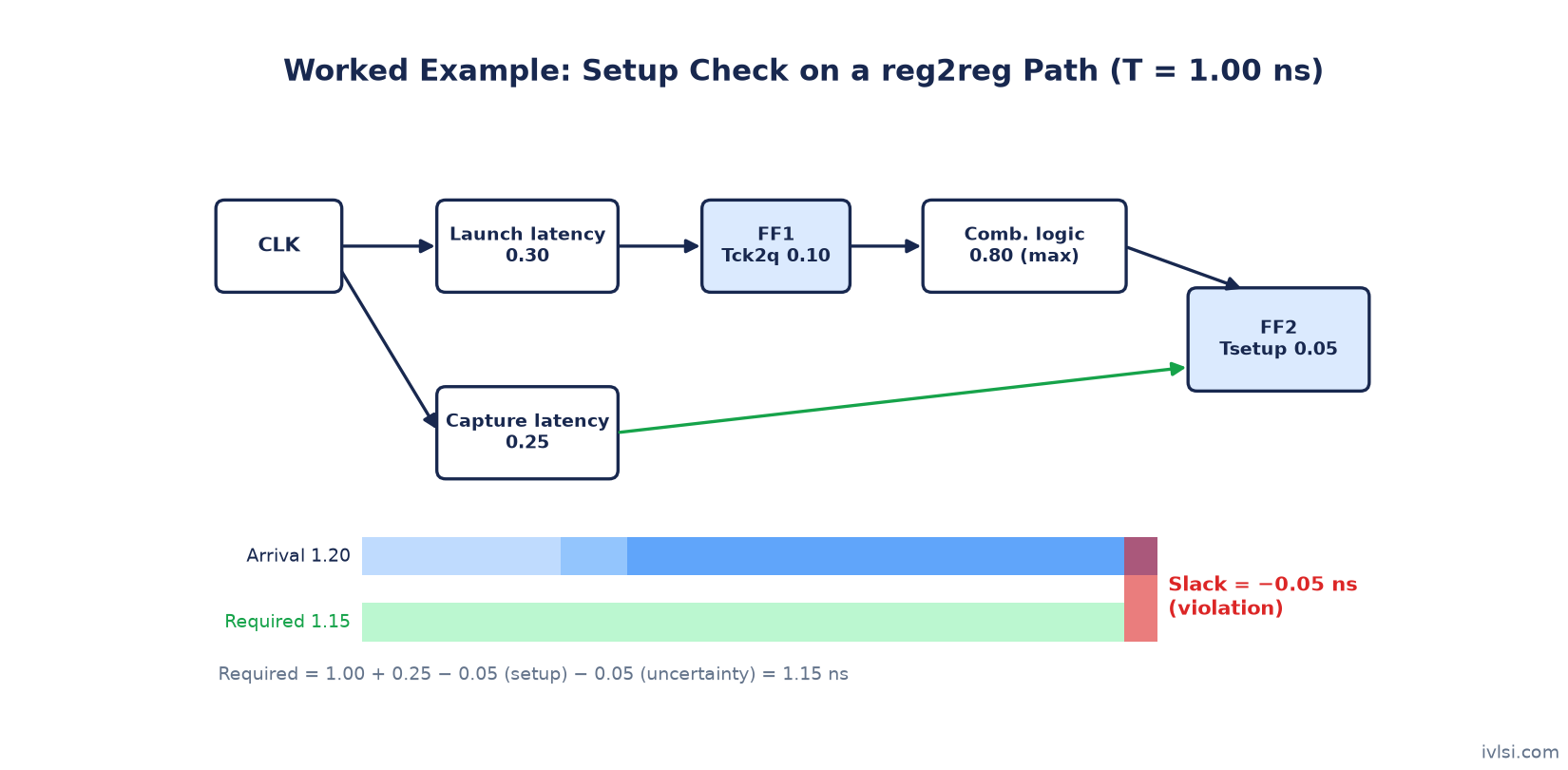
Worked Example 1: Setup Violation
| Parameter | Value (ns) |
|---|---|
| Clock period | 1.00 |
| Launch clock latency (FF1) | 0.30 |
| Capture clock latency (FF2) | 0.25 |
| Clock-to-Q of FF1 | 0.10 |
| Combinational delay (max) | 0.80 |
| Setup time of FF2 | 0.05 |
| Clock uncertainty (setup) | 0.05 |
DAT = 0.30 + 0.10 + 0.80 = 1.20 ns
DRT = 1.00 + 0.25 − 0.05 − 0.05 = 1.15 ns
Setup slack = 1.15 − 1.20 = −0.05 ns → setup violation.
Fix: upsizing two cells on the path and replacing one high-Vt cell with a low-Vt cell reduces the combinational delay by 0.08 ns to 0.72 ns. New DAT = 1.12 ns, slack = 1.15 − 1.12 = +0.03 ns. The path now meets setup. (Hold must still be re-checked, since faster cells reduce min delay too.)
Maximum Frequency from the Setup Equation
Setting the slack to zero gives the minimum clock period the path supports:
Tmin = Tck2q + Tcomb(max) + Tsetup + Tuncertainty - Tskew
where Tskew = capture latency - launch latency
Fmax = 1 / Tmin
For Example 1 before the fix: Tskew = 0.25 − 0.30 = −0.05 ns, so Tmin = 0.10 + 0.80 + 0.05 + 0.05 + 0.05 = 1.05 ns, i.e. Fmax ≈ 952 MHz – just short of the 1 GHz target, which matches the −0.05 ns slack.
Hold Check: Equation
The hold check compares the data launched at an edge with the capture at the same edge. The clock period does not appear.
Data Arrival Time (DAT)  = Launch clock latency (early) + Tck2q (min) + Tcomb (min)
Data Required Time (DRT) = Capture clock latency (late) + Thold + Tuncertainty (- CRPR)

Hold Slack = DAT - DRT
Worked Example 2: Hold Violation
| Parameter | Value (ns) |
|---|---|
| Launch clock latency (FF1) | 0.30 |
| Capture clock latency (FF2) | 0.40 |
| Clock-to-Q of FF1 (min) | 0.08 |
| Combinational delay (min) | 0.05 |
| Hold time of FF2 | 0.04 |
| Clock uncertainty (hold) | 0.03 |
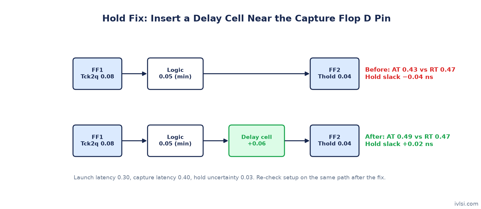
DAT = 0.30 + 0.08 + 0.05 = 0.43 ns
DRT = 0.40 + 0.04 + 0.03 = 0.47 ns
Hold slack = 0.43 − 0.47 = −0.04 ns → hold violation.
The root cause is a short data path combined with +0.10 ns positive skew (the capture clock arrives late). Fix: insert a delay cell of 0.06 ns on the data path near FF2’s D pin. New DAT = 0.49 ns, hold slack = +0.02 ns. Before signing off the fix, verify the setup slack of the same path still has more than 0.06 ns of margin, because the added delay also appears in the setup path.
Why Do Setup and Hold Violations Happen?
| Setup violation causes | Hold violation causes |
|---|---|
| Long combinational logic (too many logic levels) | Very short data paths (direct flop-to-flop, scan chains) |
| Weak or high-Vt cells, poor transitions | Large positive clock skew |
| Long wires, detours, congestion | Fast corner: FF process, high voltage |
| Negative clock skew (capture clock early) | Crosstalk speeding up a net (in hold analysis) |
| Crosstalk slowing down a net | Over-optimistic or missing hold constraints on multicycle paths |
| Overly aggressive frequency target | Excessive buffering on capture clock branch |
Also note the corner dependence: setup is usually critical at the slow corner and hold at the fast corner. In CTS and after routing, real clock skew and parasitics appear, which is why many hold violations show up only after CTS.
How to Fix Setup Violations
| Technique | How it helps | Watch out for |
|---|---|---|
| Upsize cells (higher drive strength) | Reduces cell delay and output transition | More area, power and input load on the previous stage |
| Swap HVT → SVT/LVT cells | Faster cells reduce delay | Higher leakage power |
| Buffer insertion / net splitting | Improves transition on long or high-fanout nets | Adds buffer delay if overused |
| Logic restructuring / remapping | Reduces logic depth on critical path | Must preserve function (done by synthesis/opt tools) |
| Pin swapping | Moves late-arriving signal to faster input pin | Only for logically equivalent pins |
| Better placement (pull cells closer) | Shorter wires, less RC delay | Can increase local congestion |
| Route on higher metal layers / NDR | Lower resistance on long nets | Upper layer resources, via count |
| Useful skew (delay capture clock) | Gives more time to the critical path | Reduces hold margin and slack on the next stage |
| Pipelining / relax frequency | Splits long logic into stages | RTL change, extra latency |
Related reading: Placement Optimization, Useful Skew, Metal Layers and RTL Quality Effect on Synthesis.
How to Fix Hold Violations
| Technique | How it helps | Watch out for |
|---|---|---|
| Insert delay cells / buffers on data path | Increases min data delay | Must not create setup violations |
| Downsize cells | Slower cells add delay | Can hurt transitions |
| Swap LVT → HVT cells | Slower, lower leakage | Also slows setup path |
| Place delay near capture flop D pin | Affects only that endpoint | Placement space near the flop |
| Reduce capture clock latency / skew | Reduces required time | Can affect other paths on same clock branch |
| Fix constraints (multicycle hold, false paths) | Removes false violations | Only if the path really is MCP/false |
Hold fixing is usually done after CTS, when real clock latencies are known, and it should be done with all hold corners active together so that a fix at one corner does not break another.
Setup and Hold Fixing Across the Flow
- Synthesis – fix large setup issues through logic structure; hold is usually ignored with ideal clocks. See Physical Synthesis.
- Placement – setup optimisation with estimated wires.
- CTS – real skew is introduced; first serious hold fixing.
- Post-route – optimisation with real parasitics and crosstalk (Signal Integrity and Crosstalk).
- Sign-off ECO – small targeted fixes (sizing, buffers, delay cells) followed by incremental STA.
Can a Path Have Both Setup and Hold Violations?
Yes, at different corners, or when the clock uncertainty and skew are very large compared with the period. Fixing one makes the other worse, so first check whether the clock skew or constraints are wrong. If the window between max and min data delay is too narrow, the real fix is usually reducing skew or variation, not adding cells.
Setup and Hold Interview Questions
Q1. Why can’t hold violations be fixed by reducing frequency?
Because the hold check compares launch and capture on the same clock edge, so the period does not appear in the equation.
Q2. Which corner is worst for setup and for hold?
Typically the slow corner for setup and the fast corner for hold; with temperature inversion, multiple temperatures must be checked.
Q3. How does positive skew affect setup and hold?
It increases setup slack and decreases hold slack.
Q4. Why is hold fixing done after CTS?
Before CTS the clock is ideal with zero skew, so real hold slack is unknown.
Q5. Where would you insert a hold buffer and why?
Close to the capture flop’s D pin, so it only delays the violating endpoint and not other fanouts.
Q6. What is negative setup or hold time?
A library value can be negative due to internal delays in the flop; it means data may arrive slightly after (setup) or change slightly before (hold) the clock edge.
Q7. A path fails setup by 50 ps. What would you check first?
Whether the constraints are correct, the path’s logic depth, poor transitions or long nets, skew, and whether useful skew or sizing can recover it.
Q8. What is the effect of clock uncertainty?
It reduces slack for both setup and hold, modelling jitter and margin.
FAQ
What is a setup and hold violation?
A setup violation happens when data arrives too late before the capture clock edge; a hold violation happens when data changes too soon after the clock edge.
How to fix setup and hold violations?
Setup: upsize cells, use faster Vt, buffer long nets, restructure logic, improve placement, use useful skew. Hold: insert delay cells, downsize or use slower Vt cells on the data path, adjust skew.
What is the difference between setup and hold time?
Setup time is the stable window before the clock edge; hold time is the stable window after it.
Which is more critical, setup or hold?
Hold is more critical for functionality because a hold violation makes the chip fail at any frequency; setup only limits the maximum frequency.
Related iVLSI tutorials: Static Timing Analysis (STA) in VLSI | Antenna Effect in VLSI
Conclusion
Setup and hold violations come down to two simple equations. Learn to compute arrival time, required time and slack by hand, understand how skew and corners move them, and apply the right fix from the tables above. Continue with Recovery and Removal Time and Duty Cycle & Pulse Width for related timing checks.