

A half-cycle path is a timing path that launches on one edge of a clock and captures on the opposite edge: rising to falling, or falling to rising. It gets only half a clock period for setup, it depends on the clock’s duty cycle, and it often appears where nobody planned it, such as an accidental clock inversion or a negative-edge flop in a scan chain.
This guide covers how STA builds the setup and hold checks, why setup gets harder while hold gets easier, the role of duty cycle and the clock tree, where these paths come from, and how to fix them. It includes worked examples (all numbers illustrative), a debug flowchart, interview Q&As and a FAQ. Related reading on iVLSI: Static Timing Analysis (STA) in VLSI, Setup and Hold Violations, Duty Cycle and Pulse Width, Generated Clocks in STA, Multicycle Path and False Path in STA and Difference Between Latch and Flip-Flop.
What is a half-cycle path?
In a normal single-cycle path, a positive-edge flop launches data on a rising clock edge and another positive-edge flop captures it on the next rising edge. The data has one full period, T, to get there.
In a half-cycle path, the capture flop (or the capture-side clock) uses the opposite edge:
- Rise to fall: a positive-edge flop launches at the rising edge and a negative-edge flop captures at the following falling edge. The data has the high phase of the clock.
- Fall to rise: a negative-edge flop launches at the falling edge and a positive-edge flop captures at the next rising edge. The data has the low phase.
With a 50% duty cycle, both cases give T/2. With any other duty cycle, one direction gets less than T/2 and the other gets more. The same applies when the launch and capture clocks are different but related, for example a clock and its inverted generated clock defined with create_generated_clock -invert.
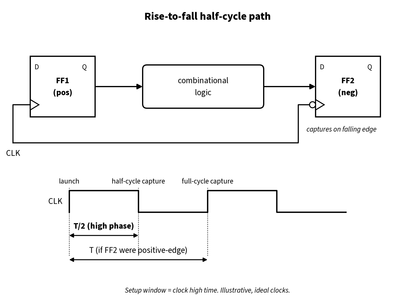
Half-cycle paths are not the same as latch paths. A latch is transparent for a whole phase and can borrow time (see Time Borrowing in VLSI). A negative-edge flop is still an edge-triggered device: it captures at one instant, the falling edge, and there is no borrowing.
How STA builds the setup and hold checks
STA works out a setup relationship and a hold relationship for every launch/capture clock pair. For a path launched and captured by the same clock, the default rules are:
- Setup: the capture edge is the closest capture-clock edge (of the right sense) that is strictly after the launch edge.
- Hold: check that the data launched by the launch edge does not corrupt the data captured by the capture edge before the setup capture edge, and that the data launched by the next launch edge does not corrupt the setup capture. The tool uses whichever of these is more restrictive.
For a full-cycle rise-to-rise path with period T, that gives a setup relation of T and a hold relation of 0. For half-cycle paths with clock high time TH and low time TL (T = TH + TL):
| Path type | Launch edge | Setup capture edge | Setup relation | Hold relation |
|---|---|---|---|---|
| Rise → rise (full cycle) | 0 | T | T | 0 |
| Rise → fall (half cycle) | 0 | TH | TH | TH − T = −TL |
| Fall → rise (half cycle) | TH | T | TL | −TH |
| Fall → fall (full cycle) | TH | T + TH | T | 0 |
For rise to fall, the hold check compares the launch at 0 with the falling edge before the setup capture, which is at TH − T. The next-launch check (launch at T against capture at TH) gives the same −TL. With a 50% duty cycle both half-cycle cases give a setup relation of +T/2 and a hold relation of −T/2.
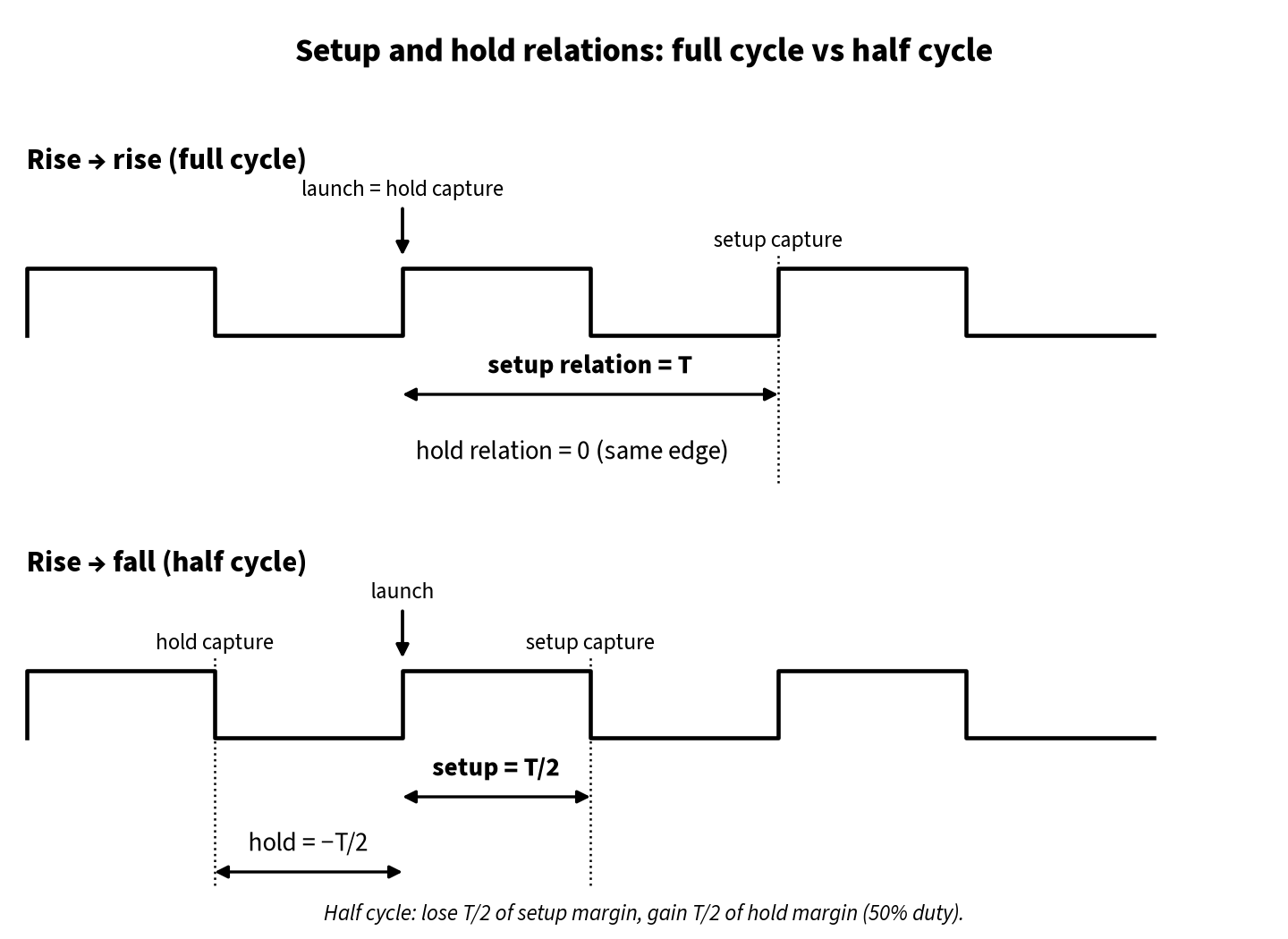
This is the key idea: compared with a full-cycle path, a half-cycle path loses T/2 of setup margin and gains T/2 of hold margin. Most half-cycle setup failures and almost all intentional uses of half-cycle paths come from that trade.
In a PrimeTime-style report, the capture clock line reads something like clock CLK (fall edge) at half the period for setup, and at a negative time for hold.
Worked example A: setup and hold on a rise-to-fall path (illustrative)
Take a 1 GHz clock (T = 1000 ps, 50% duty cycle) after CTS, with propagated clocks. A positive-edge flop FF1 launches into a negative-edge flop FF2.
| Quantity | Value (illustrative) |
|---|---|
| Launch clock latency to FF1/CK (rise) | 300 ps |
| Capture clock latency to FF2/CK (fall) | 320 ps |
| FF1 CK→Q (max / min) | 60 ps / 50 ps |
| Combinational delay (max / min) | 280 ps / 120 ps |
| FF2 setup / hold | 25 ps / 15 ps |
| Setup / hold uncertainty | 30 ps / 20 ps |
Setup (half cycle):
- Data arrival = 300 + 60 + 280 = 640 ps
- Data required = 500 (capture edge) + 320 − 25 − 30 = 765 ps
- Setup slack = 765 − 640 = +125 ps
If FF2 were a positive-edge flop, the capture edge would be at 1000 ps, the required time 1265 ps, and the slack +625 ps. The half-cycle relationship cost exactly 500 ps.
Hold (half cycle):
- Data arrival (min) = 300 + 50 + 120 = 470 ps
- Data required = −500 (hold capture edge) + 320 + 15 + 20 = −145 ps
- Hold slack = 470 − (−145) = +615 ps
For a full-cycle version the hold required time would be 0 + 320 + 15 + 20 = 355 ps, a slack of +115 ps. The half cycle added 500 ps of hold margin.
Note that the capture latency is that of the falling edge at FF2, built from fall delays through the tree, not rise delays. And whether a full-period uncertainty value is right for a half-period check is a modeling choice (see below).
Duty cycle: the hidden variable
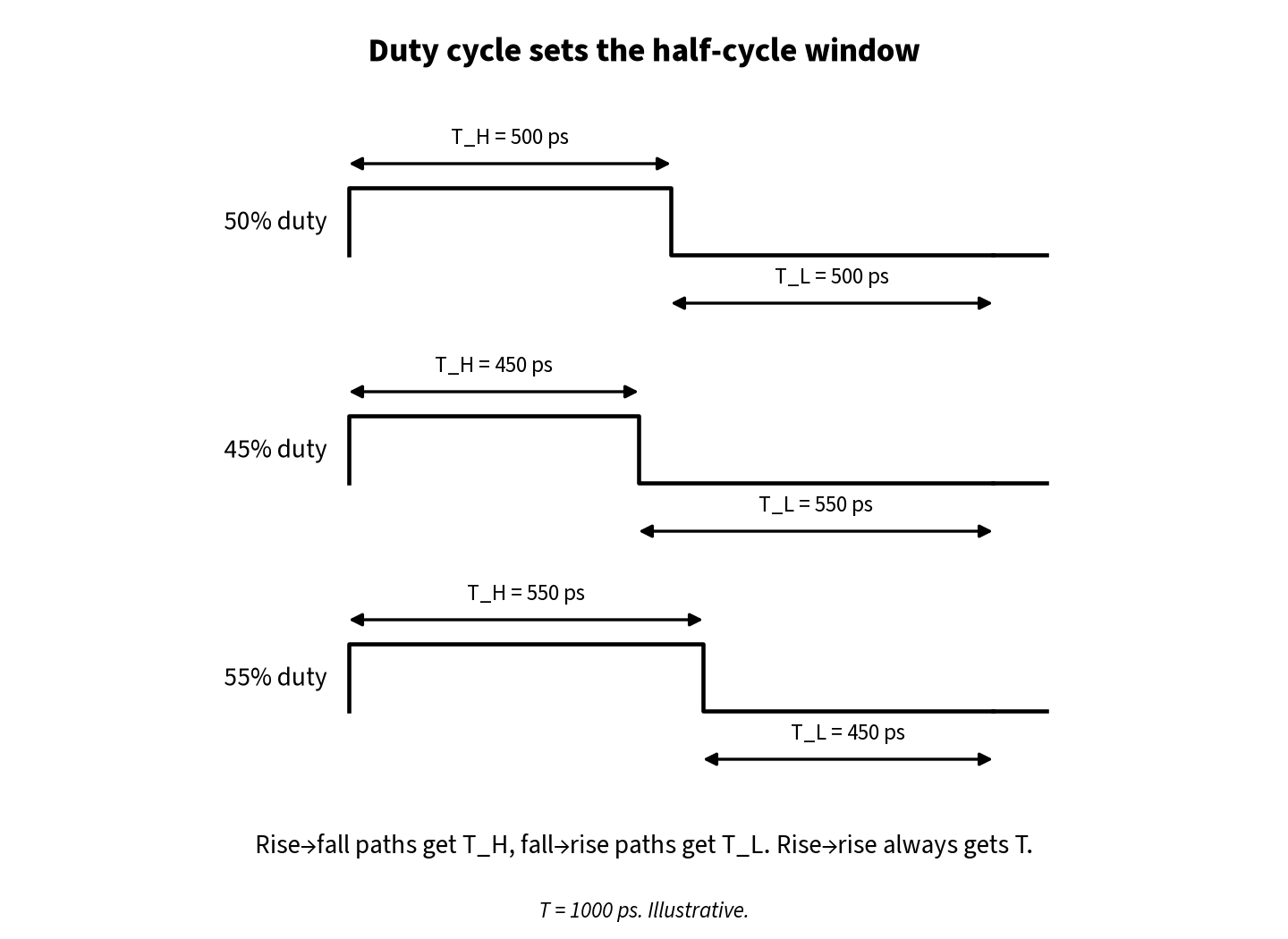
Because the setup window of a half-cycle path is one clock phase, any error in the duty cycle goes straight into slack. If the clock is high for 45% of the period instead of 50%:
- Rise-to-fall paths get TH = 450 ps instead of 500 ps. In example A the setup slack drops from +125 ps to +75 ps.
- Fall-to-rise paths get TL = 550 ps, so they gain 50 ps.
Full-cycle rise-to-rise paths do not care about duty cycle at all, which is why a duty-cycle problem often shows up only on half-cycle paths and on minimum pulse width checks. For how duty cycle is defined and how it gets distorted, see Duty Cycle and Pulse Width.
Duty cycle at the flops is not just the duty cycle at the source. The clock generator has its own tolerance, and if clock-tree buffers have unequal rise and fall delays, the high phase is stretched or squeezed at every stage (duty-cycle distortion). Inverter-based trees cancel part of this because transitions alternate. Dividers can also produce non-50% clocks by design (see Generated Clocks in STA).
In propagated-clock mode, STA already uses separate rise and fall latencies at each sink, so tree DCD is captured by the analysis. What STA cannot know is the duty-cycle error of the source, which you have to model.
Modeling duty cycle and jitter in SDC
There are two common ways to give half-cycle paths a realistic window:
# 1. Define the worst-case waveform explicitly (illustrative 45% duty)
create_clock -name CLK -period 1.0 -waveform {0 0.45} [get_ports clk]

# 2. Keep 50% but add uncertainty only for opposite-edge transfers
set_clock_uncertainty -setup 0.05 -rise_from [get_clocks CLK] -fall_to [get_clocks CLK]
set_clock_uncertainty -setup 0.05 -fall_from [get_clocks CLK] -rise_to [get_clocks CLK]
The -rise_from/-fall_to forms of set_clock_uncertainty are standard SDC and apply a separate margin to opposite-edge transfers. Option 1 only makes one direction pessimistic (a 45% waveform hurts rise-to-fall but helps fall-to-rise), so teams using it often check both waveforms. Either way, take the numbers from the clock-source and jitter specification.
Jitter needs the same thought: period jitter describes a full cycle, while a half-cycle check is sensitive to the variation of a single phase. If your clock specification gives a duty-cycle or half-period jitter value, use it for opposite-edge transfers.
OCV and CRPR on half-cycle paths
The launch flop sees a rising edge through the clock tree and the capture flop a falling edge, so even on the shared part of the tree the two analyses use different timing arcs. How much clock reconvergence pessimism removal (CRPR) credit a tool gives when launch and capture transitions differ depends on the tool and its settings, so read the CRPR line of the actual report rather than assume full credit. Background: OCV, AOCV and POCV in STA.
Where half-cycle paths come from
Some half-cycle paths are intentional. Others appear by accident. Both kinds need to be found and reviewed.
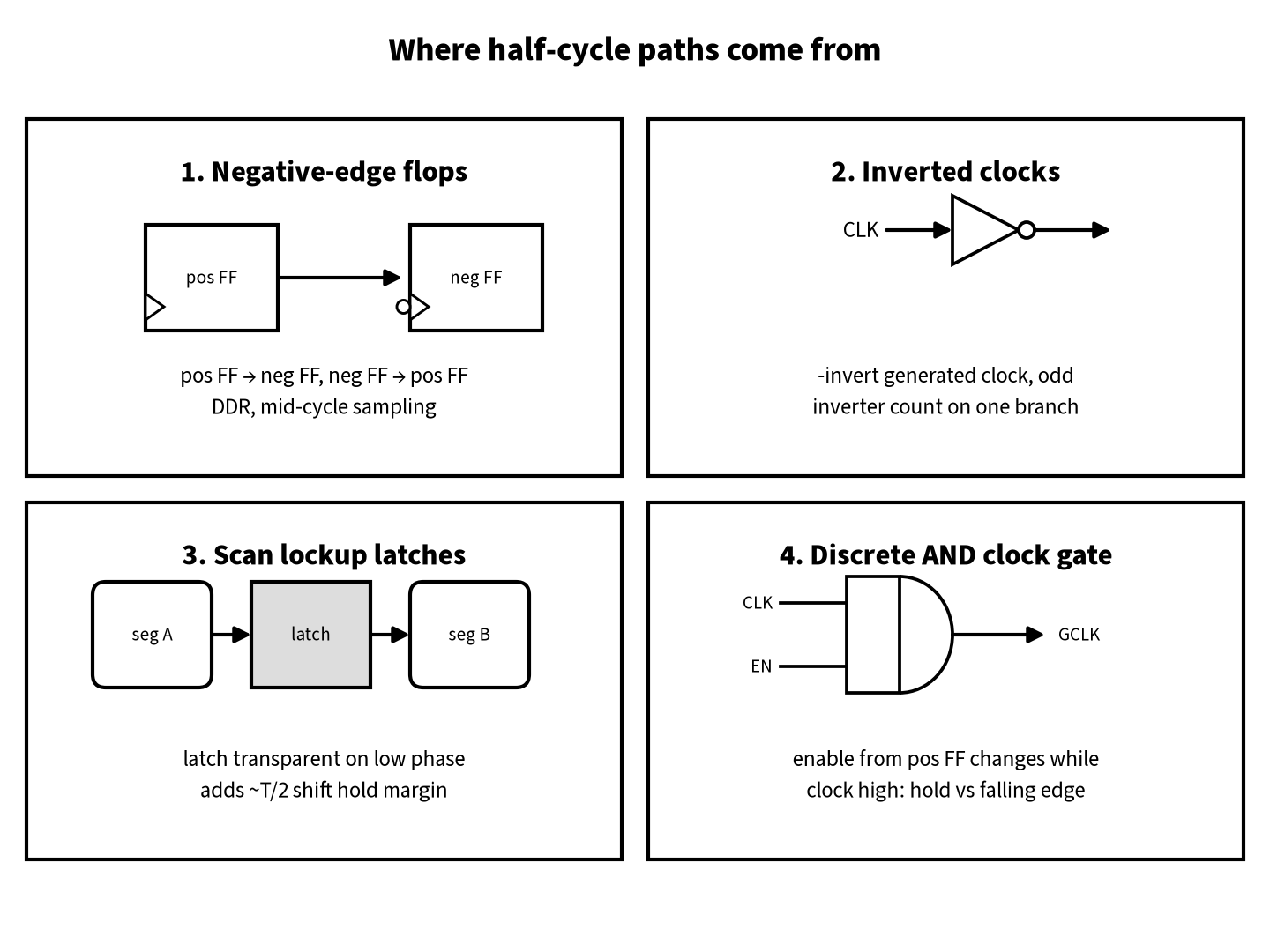
1. Intentional negative-edge flops. Used to sample mid-cycle, build DDR interfaces or split two operations within one cycle. Every transfer between them and positive-edge flops is a half-cycle path.
2. Inverted or generated clocks. A clock defined with create_generated_clock -invert, an inverting clock buffer or an odd number of inverters on one branch of the tree flips the edge sense at those sinks. If unintended, every transfer between that branch and the rest of the domain silently becomes a half-cycle path.
3. Lockup latches in scan chains. When a scan chain crosses between clock trees, skew can break shift hold. A lockup latch, transparent during the low phase of the launching clock, holds the data for about half a cycle, exactly the hold margin a half-cycle relationship gives. Negative-edge scan flops create similar shift paths, handled by chain ordering and lockup latches, and still timed at shift frequency. See Scan Chain Reordering in VLSI.
4. Clock gating checks. For a discrete AND clock gate, the enable may change only while the clock is low. An enable from a positive-edge flop changes while the clock is high, so the gating hold check is against the falling edge, a half-cycle requirement that is very hard to meet. That is a major reason ICG cells latch the enable. See Clock Gating and ICG.
Finding them
List the opposite-edge transfers and have the designer confirm each group. In PrimeTime-style tools, commands like these help (option names vary, so check your tool’s manual):
# registers clocked by the falling edge of CLK
all_registers -fall_clock [get_clocks CLK]

# worst setup paths launched by CLK and captured on its falling edge
report_timing -from [get_clocks CLK] -fall_to [get_clocks CLK] -delay_type max -max_paths 20
Fixing half-cycle setup violations
Half-cycle hold violations are rare, because the hold relation already gives T/2 of margin; when they occur, fix them like any hold issue (see Setup and Hold Violations). For setup, in rough order of preference:
- Confirm that the opposite-edge capture is intended. If the inversion is a mistake (a wrong
-invert, an odd inverter count on a branch, a wrong library cell), fix the clock or the netlist. That turns the path back into a full-cycle path and is the biggest possible gain. - Check the clock model. Make sure the waveform, the duty-cycle allowance and the uncertainty are right for opposite-edge transfers. A full-period jitter number on top of a pessimistic waveform can double-count.
- Reduce logic depth. Half a period is not much. Move logic to the full-cycle side of the negative-edge flop (logic before a positive-edge launch or after a negative-edge capture). This is an RTL or synthesis change, so agree it with the designer.
- Tighten placement and routing. Place the launch, logic and capture cells close together, upsize drivers, reduce fanout and promote long nets to higher metal layers.
- Use skew carefully. Delaying the capture falling edge (or advancing the launch) gives setup margin, but it also changes every other path on those flops. See Useful Skew in VLSI and check hold and the neighbouring paths after any change.
- Fix the clock tree. If the falling-edge latency at the capture sinks is much earlier than expected, look at duty-cycle distortion and rise/fall imbalance in the tree. See Clock Tree Synthesis (CTS).
- Change the architecture. If the path can never fit in half a period, capture on the rising edge and add a pipeline stage, or use a latch so the path can borrow time. This needs a functional review.
What not to do: don’t add a multicycle path or a false path just to make a half-cycle violation disappear. An exception is only valid if the logic really allows the extra time. See Multicycle Path and False Path in STA.
Debug flowchart: when a half-cycle path fails setup
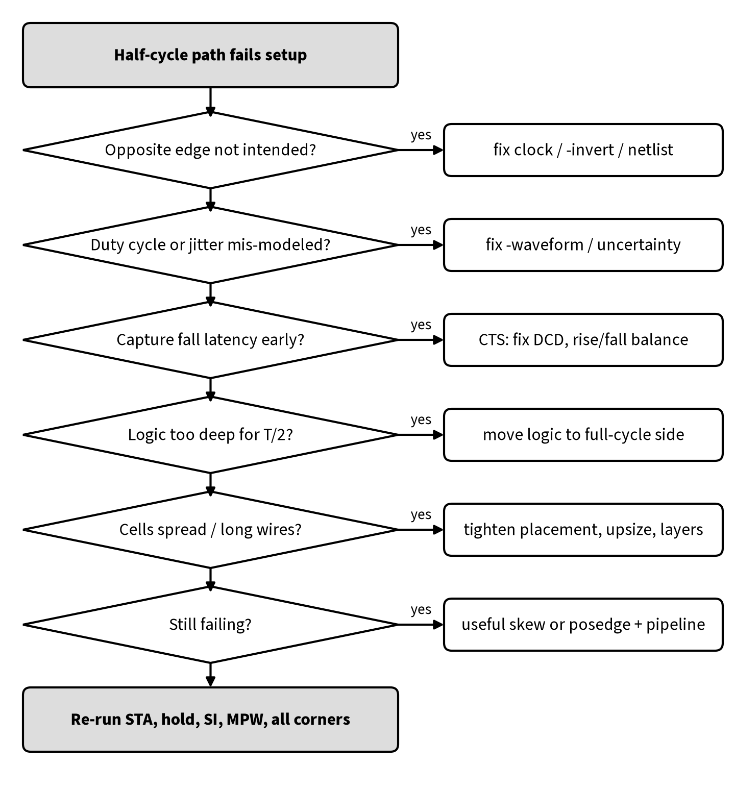
Habits that catch most problems early:
- List opposite-edge transfers at synthesis. Review every group with the designer before floorplanning.
- Look for slack values close to −T/2. A path that fails by roughly half a period is usually an unintended edge inversion, not a logic problem.
- Re-check after CTS. Ideal clocks hide rise/fall latency differences. The first propagated-clock run is where half-cycle paths usually move most.
Interview Q&As
Q1. What is a half-cycle path?
A. A timing path where the launch and capture use opposite edges of the same (or a related) clock: rise to fall, or fall to rise. With a 50% duty cycle the data gets T/2 for setup instead of T.
Q2. What are the setup and hold relations of a rise-to-fall path?
A. Setup is checked at the next falling edge, so the setup relation is the high time TH (T/2 at 50% duty). Hold is checked against the falling edge one period earlier, giving a hold relation of −TL (−T/2 at 50% duty).
Q3. Why is hold easier on a half-cycle path?
A. For a full-cycle path the hold capture edge is at the same time as the launch edge (relation 0). For a half-cycle path it is half a period before the launch edge, so the data has about T/2 of extra hold margin.
Q4. Why do half-cycle paths depend on duty cycle when full-cycle paths don’t?
A. A full-cycle path goes from a rising edge to the next rising edge, which is always one period. A half-cycle path goes from a rising edge to a falling edge or the reverse, so its window is one phase, and the phase length changes with duty cycle.
Q5. How do you model duty-cycle error for half-cycle paths?
A. Either define a worst-case waveform in create_clock -waveform, or keep 50% and add set_clock_uncertainty with -rise_from/-fall_to (and the reverse) for opposite-edge transfers. Base the values on the clock-source and jitter specification.
Q6. A path fails setup by about half the clock period. What do you check first?
A. Whether the capture (or launch) edge is inverted by mistake: a wrong generated clock, an odd number of inverters on one clock branch, or a negative-edge cell that should not be there.
Q7. How does a lockup latch use the half-cycle idea?
A. Placed between two scan segments on different clock trees, it holds the shifted data for about half a cycle. That gives enough hold margin to absorb the skew between the trees during shift.
Q8. Why is a plain AND clock gate with an enable from a positive-edge flop a problem?
A. The enable changes while the clock is high, so the gating hold check is against the falling edge. That is a half-cycle hold requirement that is hard to meet. Latch-based ICG cells avoid it.
FAQ
Are half-cycle paths bad design practice?
Not by themselves. DDR interfaces, lockup latches and some datapath designs rely on them. They just have half the setup budget, so they need to be deliberate, few in number, and reviewed.
Do half-cycle paths affect the maximum frequency?
Yes. If a half-cycle path has delay D, it effectively needs a period of about 2D plus margins, so a deep half-cycle path can limit the frequency of the whole domain.
Does a 50% duty cycle at the PLL guarantee 50% at the flops?
No. Rise/fall imbalance in the clock tree, dividers and muxes can distort it. Propagated-clock STA captures the tree part; the source tolerance has to be modeled in SDC.
Summary
- A half-cycle path launches and captures on opposite edges of a clock: rise to fall, or fall to rise.
- Compared with a full-cycle path it loses T/2 of setup margin (setup relation TH or TL) and gains T/2 of hold margin (hold relation −TL or −TH).
- Its window is one clock phase, so duty cycle, rise/fall latency and phase jitter directly affect slack. Model them with the clock waveform and opposite-edge
set_clock_uncertainty. - Half-cycle paths come from negative-edge flops, inverted or generated clocks, lockup latches and clock gating. Some of them are accidental, so list and review them early.
- To fix setup, first rule out an unintended inversion, then check the clock model, then reduce logic and distance, and only then use skew or architectural changes. Don’t use timing exceptions as a fix.
Once you know which edge the tool is really using, the rest is ordinary timing closure with half the budget.