
Somewhere below roughly 80 nm metal pitch, a single exposure on a 193 nm immersion scanner can no longer print every line cleanly. The industry’s answer, before EUV became available, was to split one layer’s pattern across two masks and print it in two steps. That is double patterning (DPT), and even on EUV-era nodes some form of multiple patterning is still used for the tightest layers. For a physical design engineer, double patterning changes how standard cells are drawn, how routers place wires, how DRC is run and even how parasitics vary.
This guide explains why double patterning exists, the two main flavours (LELE and SADP), what “coloring” and “decomposition” mean, why odd cycles cause unfixable conflicts, what stitches are, and how DPT-aware placement, routing and sign-off work. It finishes with illustrative worked examples, a debugging flowchart, interview questions, an FAQ and a summary.
Related reading: Understanding Metal Layers, Pitch, Spacing and Offset, Routing in VLSI Physical Design and Vias in VLSI Physical Design.
Why a single exposure stops being enough
Optical lithography has a resolution limit. A common way to write it is the Rayleigh criterion for the smallest printable half-pitch:
half-pitch = k1 × λ / NA
where λ is the exposure wavelength, NA is the numerical aperture of the lens, and k1 is a process factor. For a single exposure, k1 has a theoretical lower limit of 0.25. With 193 nm light and water immersion (NA around 1.35), that puts the smallest single-exposure half-pitch at roughly 36 nm, which is a pitch of about 72 nm, and practical processes cannot run right at the theoretical limit. Anything tighter needs another trick.
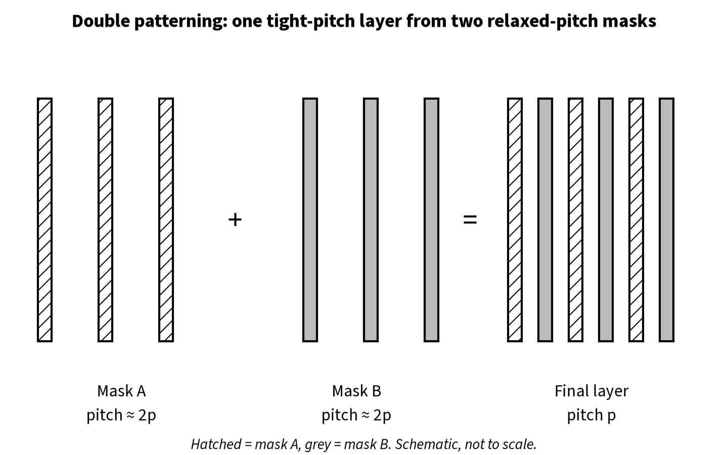
Double patterning gets around the limit by never asking one mask to print the full density. If the target layer has pitch p, each of the two masks only carries every other feature, so each mask sees a pitch of about 2p. Each exposure stays printable, and the combined result has the tight pitch the design needs.
The two main flavours: LELE and SADP
LELE (litho-etch-litho-etch)
In LELE, the layer is printed with mask A, etched, then printed with mask B and etched again. The design is split into two sets of shapes, conventionally called two colors (or masks). It is flexible: almost any layout can be split as long as no two shapes that are too close end up on the same mask.
Its weakness is overlay. The second exposure is aligned to the first, and any misalignment shifts all mask-B shapes relative to mask-A shapes. That changes the spacing, and therefore the coupling capacitance, between neighbouring wires of different colors. LELE also needs two full lithography and etch passes, which costs time and money.
Variants such as LELELE (triple patterning) extend the idea to three masks for even tighter pitches, at more cost and a harder coloring problem.
SADP (self-aligned double patterning)
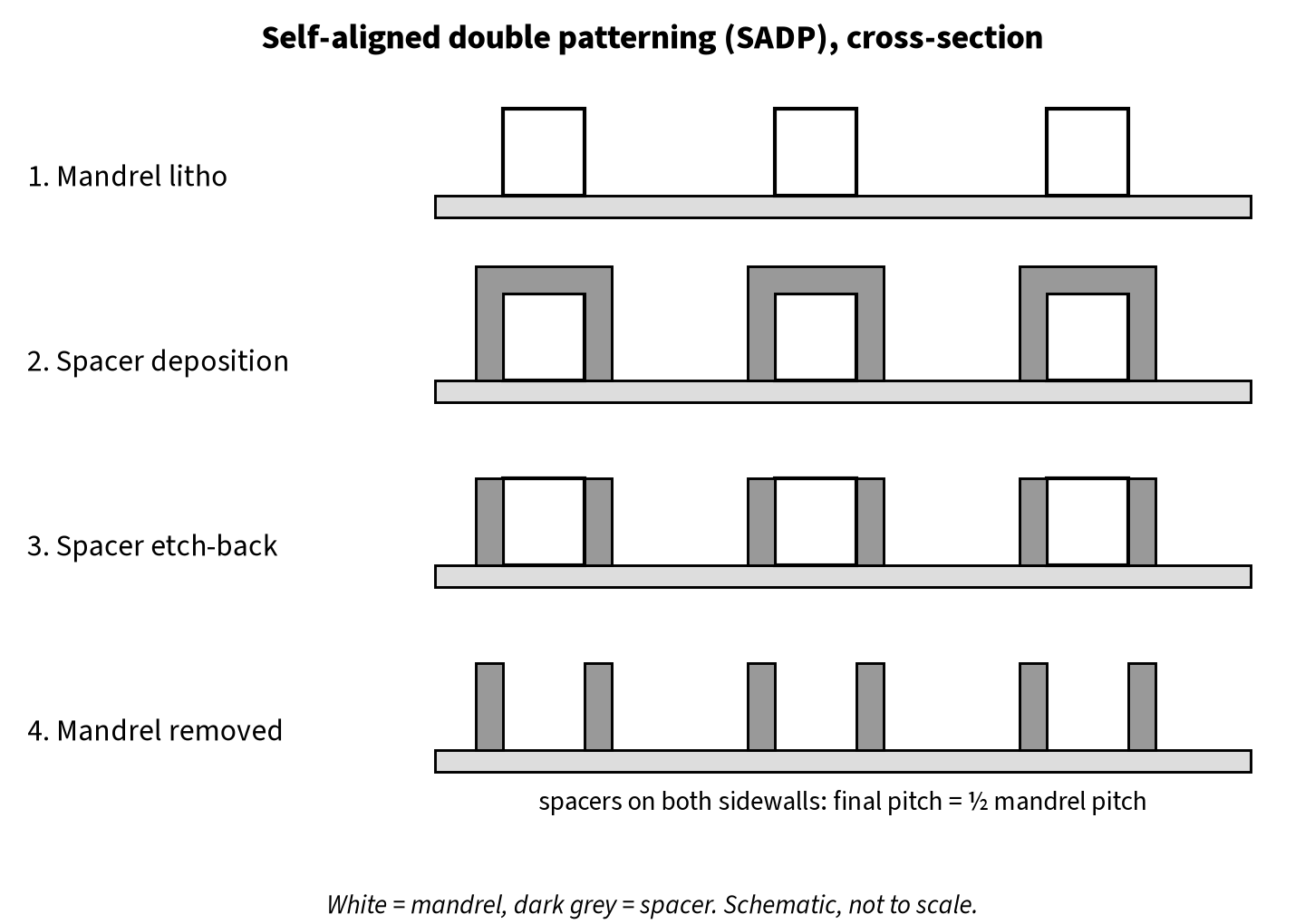
In SADP, one lithography step prints a mandrel pattern. A thin film is deposited conformally over it, then etched back so only spacers remain on the mandrel sidewalls. The mandrel is removed, and the spacers become the hard mask for the final lines (or, in some schemes, define the gaps between them). Because both sides of each mandrel produce a spacer, the final pitch is half the mandrel pitch, and since the spacers are formed by deposition, not by a second exposure, there is no mask-to-mask overlay between neighbouring lines.
The trade-off is that SADP is far less flexible. It naturally produces regular, unidirectional gratings. Line ends, jogs and irregular widths need additional cut or block masks, and the layout has to follow strict rules about which tracks can be used and where lines can end. Repeating the spacer step gives SAQP (self-aligned quadruple patterning) for even tighter pitches. SADP and SAQP are widely used for fins and for the tightest metal layers because the regularity and overlay immunity are worth the design restrictions.
Coloring and decomposition
For LELE-style double patterning, the key design-side task is decomposition: assigning every shape on a DPT layer to mask A or mask B. In EDA tools this is called coloring, and the two masks are often shown as two colors in the layout viewer.
The rule is simple. Every layer has a minimum spacing for shapes on the same mask (call it S_same), which is larger than the minimum spacing allowed for shapes on different masks (S_diff). Any two shapes closer than S_same must be on different masks. If they are also closer than S_diff, they cannot be printed at all.
Tools turn this into a graph problem:
- Each shape (or shape fragment) is a node.
- An edge connects any two shapes closer than S_same. This is a conflict edge: the two nodes must get different colors.
- Coloring the layout means two-coloring this conflict graph.
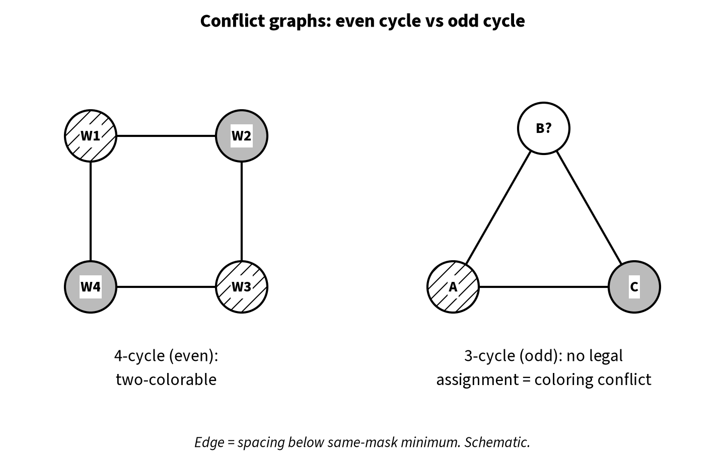
A graph can be two-colored if and only if it has no odd cycle. If three shapes are all mutually closer than S_same, or more generally if the conflict edges form a loop with an odd number of shapes, there is no legal assignment. That is a coloring conflict, often called an odd-cycle violation. No amount of re-coloring fixes it; the geometry itself has to change.
Stitches
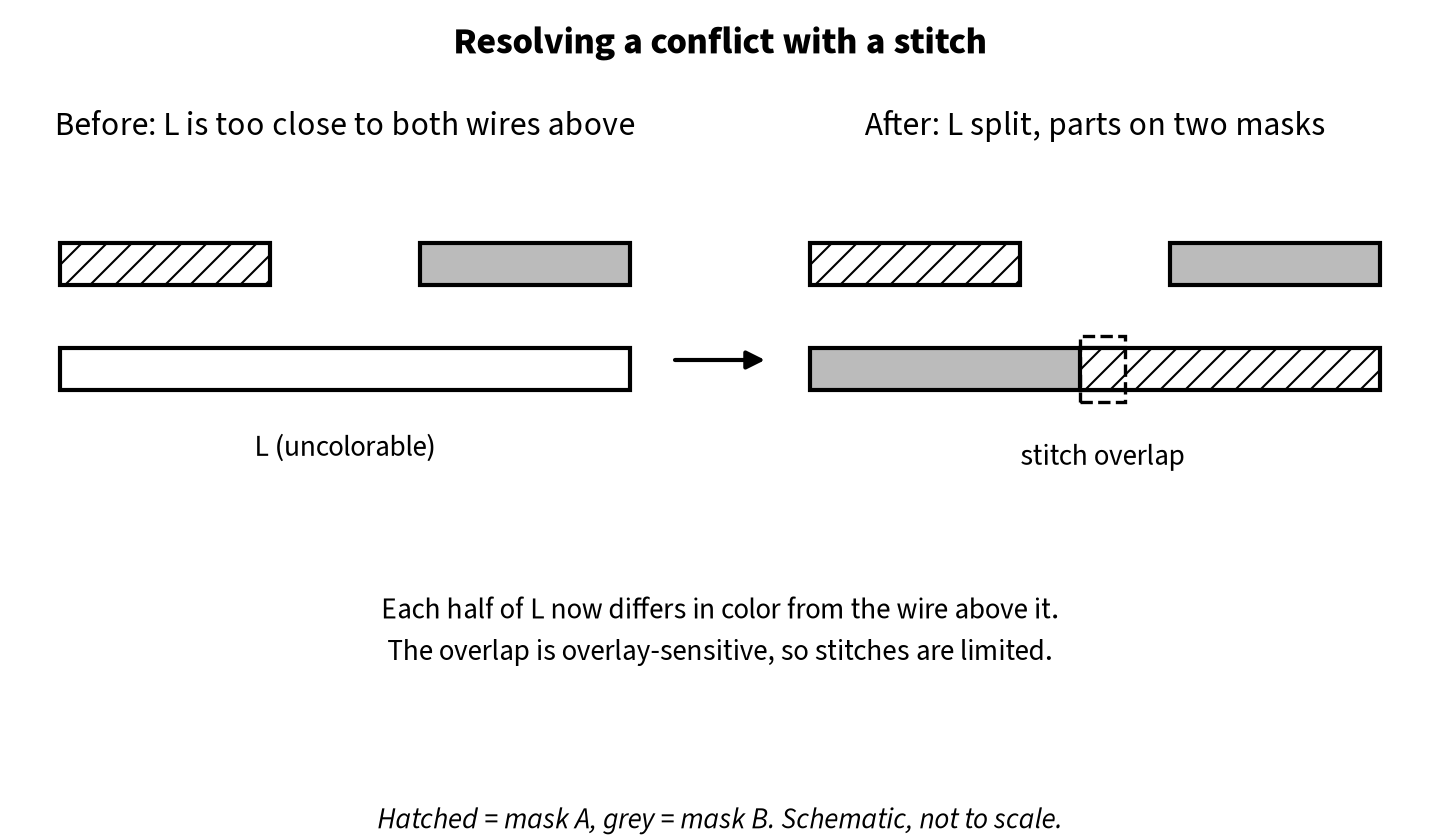
Sometimes one long shape takes part in an odd cycle only because of one end. A stitch breaks that shape into two parts, gives each part a different color, and overlaps them slightly so they print as one continuous wire. Splitting a node in the graph can remove the odd cycle.
Stitches are not free. The overlap region is sensitive to overlay and line-end effects, so it can narrow the wire, raise resistance or create a yield weak point. Processes limit where stitches are allowed (for example, not too close to line ends, vias or bends), and the decomposition tools try to minimize their number. The research literature treats conflict and stitch minimization as a combined optimization problem; Kahng et al. (ICCAD 2008) and Yuan, Yang and Pan (ISPD 2009) are well-known early papers on it.
Colorless and colored flows
Two broad design methodologies exist, and which one you use depends on your technology and its rule deck.
- Colorless (decomposition at sign-off): the designer draws in one layer, follows DPT-friendly spacing rules, and a decomposition step (by the tool or the foundry flow) assigns masks later. The design side mainly checks that the layout is decomposable, meaning no odd cycles.
- Colored (pre-colored) flow: shapes carry their mask assignment in the database, often as a mask attribute on each shape or track. Standard cells, the routing tracks and sometimes power rails are assigned colors in advance, and the router honours them. This gives the designer control over which nets share a mask, which matters for timing-sensitive nets because of the overlay-driven capacitance variation described below.
In LEF/DEF, mask information can be carried on shapes and vias (DEF supports MASK statements on routing and via shapes), so a colored design can pass its mask assignment between tools.
What double patterning changes in each step of the flow
Standard cells and placement
Cell layouts on DPT layers are pre-colored and verified to be decomposable on their own. The trouble starts at cell boundaries: two cells that are individually clean can create a conflict when they abut if shapes near their edges land too close together on the same mask. Libraries handle this with boundary rules, color-aware cell variants, or placement rules that restrict which cells may abut or how they align to the colored track grid. The placer has to respect these rules during legalization, much like the diffusion-break and cell-edge rules covered in PODE vs CPODE.
Routing
The router is where most DPT work happens. A DPT-aware router:
- Treats same-mask spacing and different-mask spacing as separate rules.
- Checks for odd cycles as it routes, not only at the end, so it does not paint itself into an uncolorable corner.
- In a colored flow, routes on tracks with fixed colors, so a net’s color is decided by which track it uses.
- Avoids patterns that are known to be hard: very short wires between two neighbours, tight line-end to line-end spacing and jogs near other wires.
Expect DPT layers to cost some routing resource. Rules for line ends and same-mask spacing remove options the router would otherwise use, which can raise congestion on the lower metals.
Extraction and timing
In LELE, an overlay shift between mask A and mask B moves every B-colored wire relative to its A-colored neighbours. One neighbour gets closer and the other farther away, which changes coupling capacitance. Technologies that use LELE often add extraction corners or mask-shift variation to capture this, and timing has to be closed across them. Same-color neighbours do not see this effect because they were printed in one exposure. This is one reason a colored flow can be attractive for critical nets such as clocks: you can control which neighbours share a mask. Coupling changes also feed into crosstalk analysis; see Signal Integrity and Crosstalk.
Physical verification
DRC on a DPT layer runs extra checks: same-mask spacing, different-mask spacing, odd-cycle detection, stitch rules and, in a colored flow, checks that every shape has a valid mask. Odd-cycle reports usually list the shapes in the loop, which is the starting point for debugging.
Worked example 1: three parallel wire ends (illustrative)
All numbers below are illustrative, not from any real process.
Assume a DPT metal layer with:
- S_diff (minimum spacing, different masks) = 32 nm
- S_same (minimum spacing, same mask) = 64 nm
Three short wires A, B and C end near each other in a triangle. The spacings are A to B = 40 nm, B to C = 40 nm and A to C = 48 nm.
All three spacings are below S_same, so A, B and C each need a different color from the other two. That is a three-node odd cycle, and with only two masks there is no legal answer. The DRC reports a coloring conflict.
Fixes, in rough order of preference:
- Pull one wire end back so that, for example, A to C becomes at least 64 nm. The A–C edge disappears, the graph becomes a simple chain, and A and C can share a color.
- Move one wire to another track or a different layer for that segment.
- Stitch, if one of the shapes is long enough and stitch rules allow it.
Worked example 2: an even cycle that is fine (illustrative)
Four wires form a square of conflict edges: W1–W2, W2–W3, W3–W4 and W4–W1, each at 40 nm, while the diagonals W1–W3 and W2–W4 are both at 70 nm (above S_same). This is a four-node cycle, which is even. Color W1 and W3 as mask A and W2 and W4 as mask B, and every conflict edge connects different colors. No change is needed.
The lesson: tight spacing by itself is not a violation. The question is whether the conflict graph has an odd loop.
Worked example 3: overlay and coupling on a clock net (illustrative)
A clock wire on mask A runs between two signal wires, one on mask A and one on mask B, all at the same drawn spacing. If mask B shifts toward the clock wire during the second exposure, the clock-to-B spacing shrinks and its coupling capacitance rises, while the clock-to-A spacing does not change.
Consequences:
- Clock net capacitance and delay vary with the overlay value, so clock skew can differ between extraction corners.
- If the B-colored neighbour switches, the noise coupled onto the clock also grows.
Typical mitigations are to put the clock on a track with same-color neighbours where the flow allows it, add shielding, or use a wider non-default rule with extra spacing. These are standard clock-routing practices that also help with DPT.
Debugging and fixing DPT violations
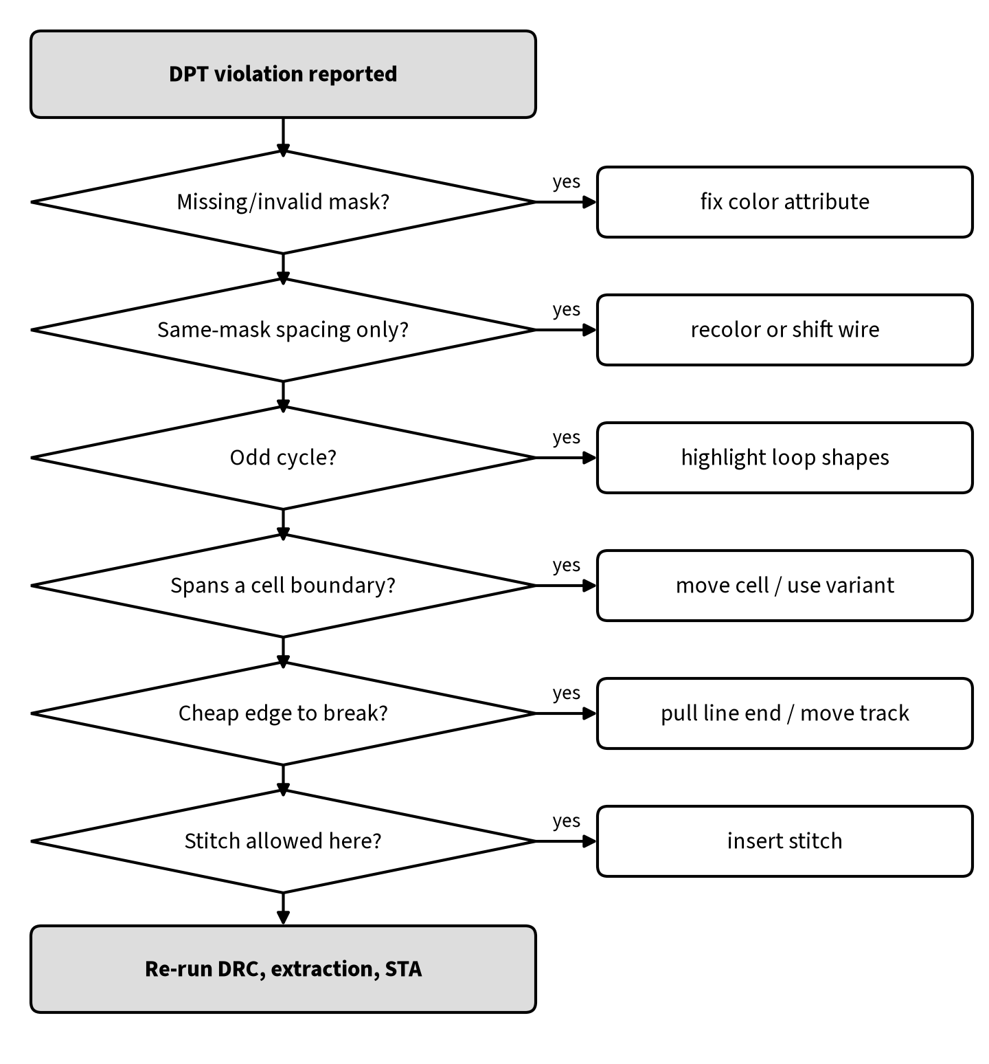
- Confirm the layer and the rule. Is the violation same-mask spacing, an odd cycle, a stitch rule or a missing mask assignment? Each has a different fix.
- Find the loop. For an odd cycle, highlight every shape in the reported cycle. Often one edge is much easier to break than the others.
- Check whether a cell boundary is involved. If the cycle spans two abutted cells, the fix may be a placement change or a different cell variant rather than a routing change.
- Break the cheapest edge. Pull back a line end, shift one wire by a track, or move a short segment to another layer.
- Stitch only if allowed and if no geometric fix is available.
- Re-run DRC, extraction and timing. Geometry changes and re-coloring can change coupling and therefore timing and SI.
Interview questions and answers
Q1. What is double patterning and why is it needed?
It splits one layer’s pattern across two masks so that each exposure only prints about twice the final pitch. It is needed when the target pitch is below what a single 193 nm immersion exposure can resolve.
Q2. What is the difference between LELE and SADP?
LELE uses two separate lithography and etch steps with two masks, so it is flexible but sensitive to overlay between the masks. SADP uses one mandrel exposure and sidewall spacers, so neighbouring lines are self-aligned with no mask-to-mask overlay, but layouts must be very regular and need cut or block masks for line ends.
Q3. What is a coloring conflict?
A set of shapes whose conflict graph contains an odd cycle, so they cannot be split into two masks without two too-close shapes sharing a mask. It must be fixed by changing the geometry or by a stitch.
Q4. Why can an even cycle be colored but an odd cycle cannot?
Two-coloring alternates colors around a loop. An even loop returns to the start with the opposite of the last color, which is consistent. An odd loop forces the first and last shapes to share a color even though they are in conflict.
Q5. What is a stitch, and what are its drawbacks?
A split of one shape into two differently colored parts with a small overlap. It can resolve a conflict, but the overlap is sensitive to overlay and can narrow the wire, raise resistance or reduce yield, so stitches are limited and minimized.
Q6. How does double patterning affect timing?
Through overlay. A shift between the masks changes the spacing between differently colored neighbours, so coupling capacitance varies. Extraction may need mask-shift corners, and critical nets may be colored deliberately.
Q7. Why can two DRC-clean cells cause a DPT violation when placed next to each other?
Shapes near the cell edges can form new conflict edges across the boundary, creating an odd cycle that neither cell has alone. Libraries and placers use boundary and coloring rules to prevent it.
Q8. Did EUV make double patterning obsolete?
Not completely. EUV lets many layers return to single exposure, but the tightest pitches can still require EUV multiple patterning or self-aligned schemes, and older DUV-based nodes continue to use double patterning.
FAQ
Is DPT only about metal layers?
No. Fins, gates and some via layers on advanced nodes also use multiple patterning, though physical design engineers mostly deal with it on the lower metal and via layers.
Do I need to color my design myself?
It depends on the technology and flow. In a colorless flow, decomposition happens later and you only need decomposable layouts. In a colored flow, cells and routing carry mask assignments and the tools handle most of it, but you may set colors for critical nets.
What does “mask shift” mean in an extraction deck?
It models the overlay error between the two masks of an LELE layer, so the extracted capacitance covers the range of possible shifts.
Can a coloring conflict be waived?
Generally no. If the shapes cannot be assigned to two masks, the layer cannot be manufactured as drawn.
Summary
- Double patterning splits one layer across two masks so each exposure prints about twice the final pitch, getting past the single-exposure resolution limit.
- LELE is flexible but overlay-sensitive; SADP is self-aligned and overlay-immune but demands regular, track-based layouts and extra cut masks.
- Decomposition is two-coloring a conflict graph; odd cycles cannot be colored and must be fixed in geometry or with a stitch.
- DPT affects cell design, placement legality, routing rules, extraction corners and DRC.
- Debug odd cycles by finding the loop and breaking its cheapest edge, then re-run DRC, extraction and timing.
References
- Multiple patterning (overview of LELE, SADP, SAQP and related techniques): https://en.wikipedia.org/wiki/Multiple_patterning
- A. B. Kahng, C.-H. Park, X. Xu and H. Yao, “Layout decomposition for double patterning lithography,” ICCAD 2008: https://doi.org/10.1109/ICCAD.2008.4681616
- K. Yuan, J.-S. Yang and D. Z. Pan, “Double patterning layout decomposition for simultaneous conflict and stitch minimization,” ISPD 2009: https://doi.org/10.1145/1514932.1514958
- H. Zhang, Y. Du, M. D. F. Wong and R. Topaloglu, “Self-aligned double patterning decomposition for overlay minimization and hot spot detection,” DAC 2011: https://doi.org/10.1145/2024724.2024741