

Most SoCs have clocks that don’t come straight from a port: a divide-by-2 register, a PLL output, a clock mux. STA has to know what those internal waveforms look like and where they come from. That is the job of generated clocks, defined in SDC with create_generated_clock. Get them wrong and you get unclocked registers, missing hold checks, or slack that is fine in STA but not on silicon.
This guide covers why STA cannot infer them, the options that matter, source latency, clock muxes and PLLs, master-to-generated crossings and debugging. It includes worked examples (all numbers illustrative), a debug flowchart, interview Q&As and a FAQ. Related reading on iVLSI: Static Timing Analysis (STA) in VLSI, Standard Design Constraints (.sdc), Setup and Hold Violations, Multicycle Path and False Path in STA, OCV, AOCV and POCV in STA, Clock Tree Synthesis (CTS) and Clock Gating and ICG.
What is a generated clock?
A generated clock is a clock whose waveform is derived from another clock, called the master clock. You declare the master with create_clock (usually on a port, a PLL output or a black-box pin). You declare the derived clock with create_generated_clock on the internal pin where the new waveform appears: the Q pin of a divider flop, the output of a PLL, or the output of a clock mux.
The key property is that a generated clock is tied to its master:
- Its edges are described as a function of master edges (divide, multiply, pick edges, shift, invert).
- Its source latency includes the delay from the master clock source to the generated clock’s definition point.
- It stays synchronous with the master, so STA times paths between the two domains with the correct edge relationship.
A plain create_clock on the same internal pin has none of that: it starts at time zero at that pin. This is the most common generated-clock mistake (see worked example A).
Why STA cannot infer the divided clock
Clocks propagate through combinational cells: buffers, inverters, ICGs, mux data inputs. They do not propagate through the clock-to-Q arc of a sequential cell. A flop’s Q pin is a data output, so if a divide-by-2 register drives the clock pins of other flops, those flops see no clock unless you declare one. They show up as unclocked registers, and every path into or out of them goes untimed. There is no slack to warn you; only clock checks catch it.
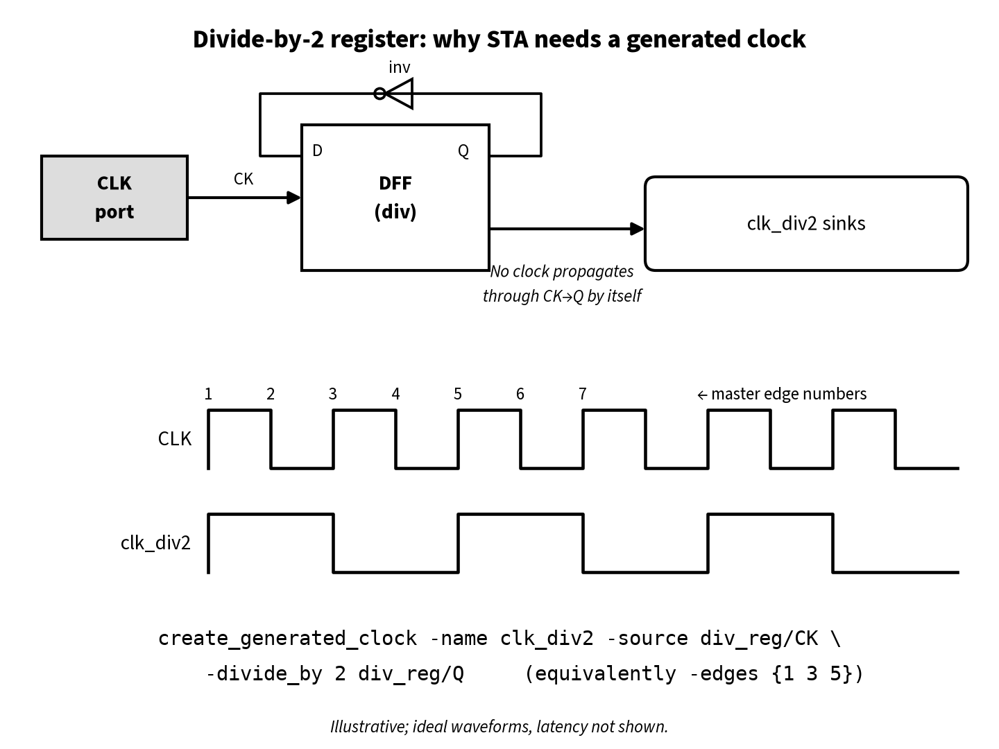
The fix is one SDC line (shown with its master clock):
create_clock -name CLK -period 2.0 [get_ports clk]
create_generated_clock -name clk_div2 \
    -source [get_pins div_reg/CK] -divide_by 2 [get_pins div_reg/Q]
The -source option names a pin that carries the master clock, and the last argument is the pin where the generated clock is defined. Pointing -source at the divider’s CK pin makes the CK→Q path explicit; the port also works if the tool can trace a path to the definition point.
The options that matter
| Option | What it does | Typical use |
|---|---|---|
-source pin |
Pin carrying the master clock; the reference for edges and source latency | Always required |
-divide_by N |
Period × N, edges taken from master rising edges | Register dividers |
-multiply_by N |
Period ÷ N | PLL/DLL outputs |
-duty_cycle % |
Duty cycle, used with -multiply_by |
PLL outputs with known duty |
-edges {a b c} |
Builds the waveform from master edge numbers | Odd dividers, falling-edge dividers, pulses |
-edge_shift {x y z} |
Shifts each listed edge by a time value | Fine waveform offsets |
-invert |
Inverts the derived waveform | Inverted divider outputs |
-combinational |
Source latency follows only combinational logic from master to target | Clock dividers by 1, muxes, clock outputs |
-master_clock clk |
Selects which master when several clocks reach -source |
Muxed or multi-clock sources |
-add |
Adds a clock to a pin without replacing an existing one | Several generated clocks on one mux output |
Extras vary by tool, but these core options are standard SDC.
Using -edges
-edges is the most flexible option and the one interviewers like best. Master clock edges are numbered from 1: edge 1 is the first rising edge, edge 2 the following falling edge, edge 3 the next rising edge, and so on. Odd numbers are master rising edges and even numbers are master falling edges. You list exactly three edges: the generated clock’s rise, its fall, and its next rise.
-edges {1 3 5}is a divide-by-2 with 50% duty cycle, the same as-divide_by 2.-edges {2 4 6}is a divide-by-2 launched from master falling edges, which is what you get from a negative-edge-triggered divider.-edges {1 3 7}is a divide-by-3 that is high for one master period and low for two (one-third duty).-edges {1 5 7}is a divide-by-3 that is high for two periods and low for one.-edges {1 4 7}is a divide-by-3 with 50% duty cycle. Its falling edge sits on a master falling edge, so the real circuit has to use both master edges.
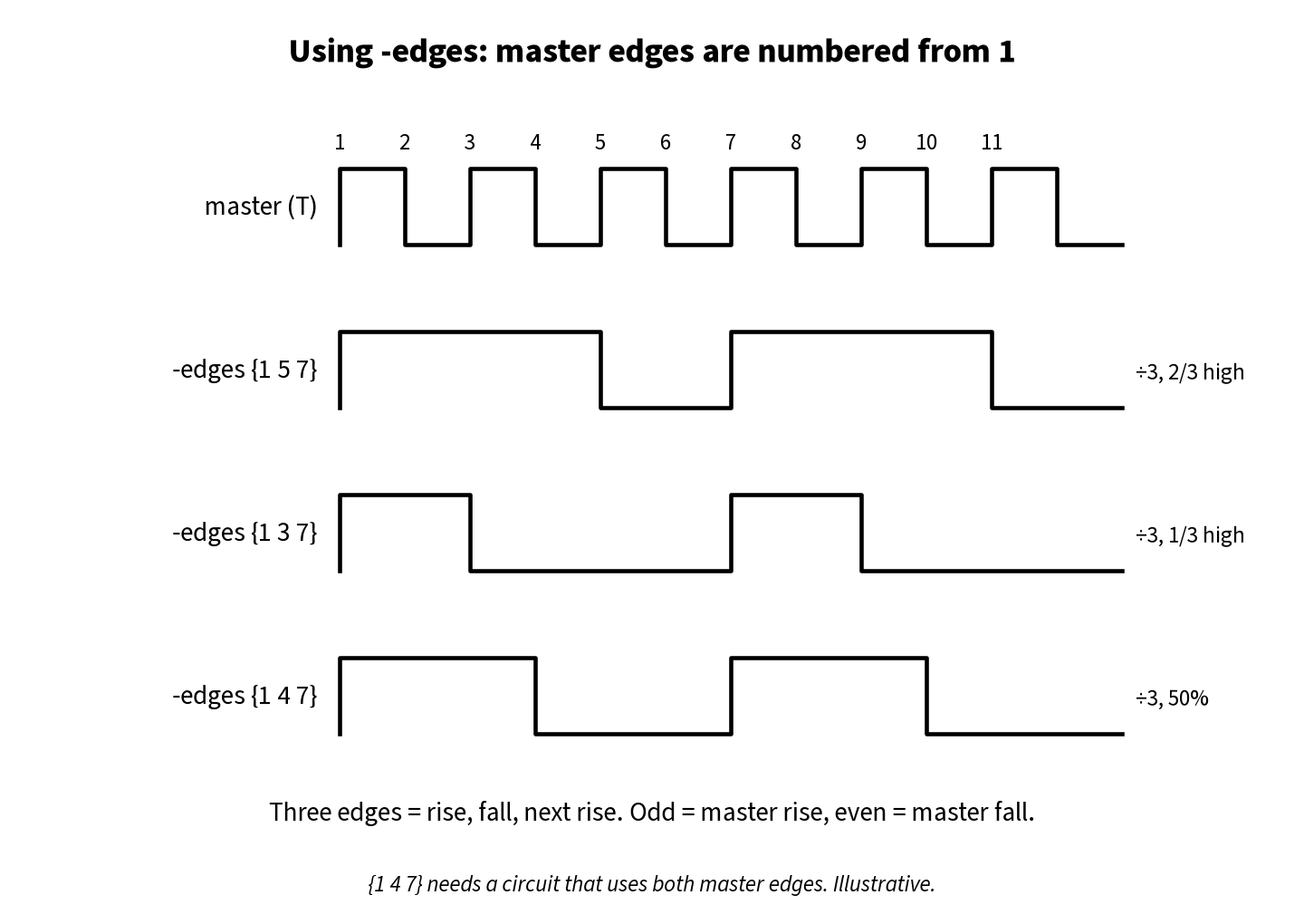
The rule is simple: the SDC waveform has to describe what the RTL actually builds. A -divide_by 3 alone tells the tool nothing about the duty cycle you need for half-cycle paths or minimum-pulse-width checks. If the divided clock drives negative-edge flops or latches, describe the exact edges. See Duty Cycle and Pulse Width and Time Borrowing for why the high and low phases matter.
Source latency: where generated clocks earn their keep
A clock’s arrival at a sink is its source latency (from the clock’s ideal source to its definition point) plus its network latency (from the definition point to the sink). For a primary clock on a port, the source latency is whatever you model with set_clock_latency -source for off-chip delay. For a generated clock, the source latency is the path from the master source to the generated clock pin: the master clock tree up to the divider’s CK pin plus the divider’s CK→Q delay.
In propagated-clock analysis (post-CTS), STA tools trace that path and add it to the generated clock automatically. This is why a generated clock is right and a stray create_clock on the Q pin is wrong. Before CTS, with ideal clocks, latency comes from your ideal-latency settings, so set them deliberately.
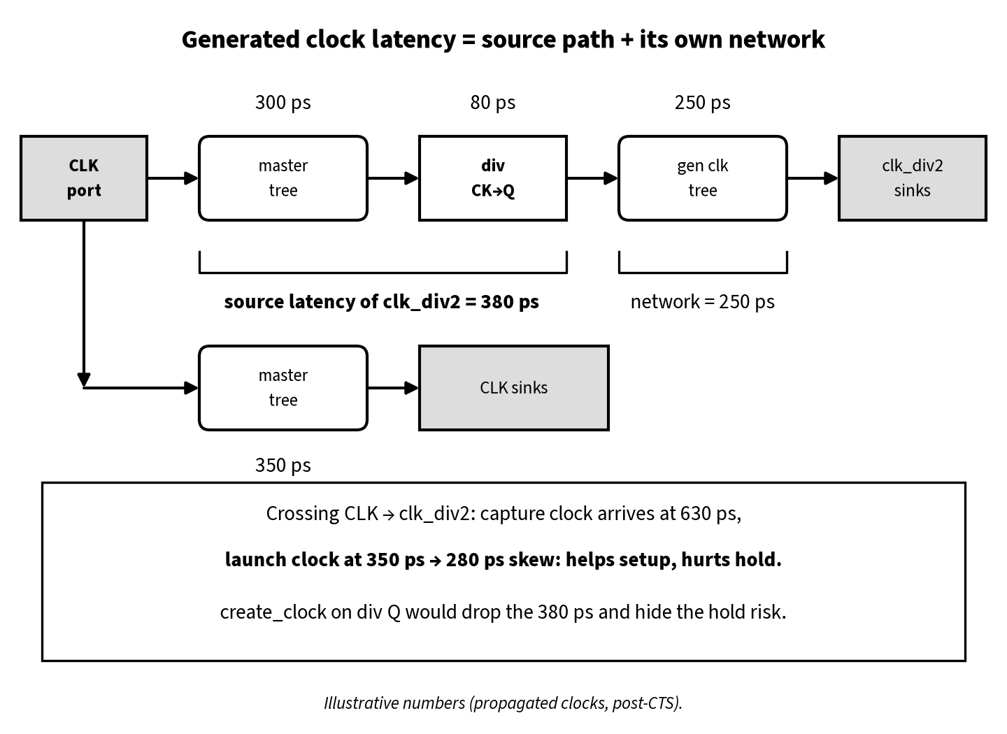
Worked example A: the cost of create_clock on a divider (illustrative)
All numbers are made up for teaching. They are not from any library or foundry.
- Master
CLK: period 2.0 ns, defined at the port. - Master tree to ordinary CLK sinks: 350 ps.
- Master tree to the divider flop’s CK pin: 300 ps. Divider CK→Q: 80 ps.
clk_div2tree from div_reg/Q to its sinks: 250 ps.- A path from a CLK-domain flop (FF1) to a clk_div2-domain flop (FF2): clock-to-Q 60 ps, logic 100 ps, FF2 hold requirement 20 ps.
Correct constraint (generated clock). The capture clock arrives at FF2 at 300 + 80 + 250 = 630 ps. The hold check is a same-edge check at time 0:
- Data arrival = 350 (launch clock) + 60 + 100 = 510 ps
- Hold required = 630 + 20 = 650 ps
- Hold slack = 510 − 650 = −140 ps, a real violation.
Wrong constraint (create_clock -period 4.0 on div_reg/Q). The new clock starts at the Q pin at time 0, so the 380 ps of source latency vanishes. Capture arrival drops to 250 ps:
- Hold required = 250 + 20 = 270 ps
- Hold slack = 510 − 270 = +240 ps, a false pass.
The silicon has the 380 ps whether or not your SDC does. With the wrong constraint the hold violation is hidden until the part fails. (For a falling-edge divider, create_clock also loses the half-period offset.) The fix for the real −140 ps is physical: balance the clk_div2 sinks against the CLK sinks in CTS, or let hold fixing insert delay. See Setup and Hold Violations and Useful Skew for how skew trades setup against hold.
Timing between master and generated domains
STA times master/generated crossings using the most restrictive launch/capture edge pair over the common period.
Worked example B: fast-to-slow and slow-to-fast (illustrative)
Take CLK at 2 ns and clk_div2 at 4 ns, with edges aligned at time 0 (ideal clocks, latency ignored).
CLK → clk_div2 (fast to slow). CLK launches at 0, 2, 4 … and clk_div2 captures at 0, 4, 8 … A launch at 2 ns must be captured at 4 ns, so the default setup budget is 2 ns, one fast period. The default hold check is the same-edge check (launch 4, capture 4), with a 0 ns relationship.
clk_div2 → CLK (slow to fast). A launch at 0 is captured by the next CLK edge at 2 ns, so the setup budget is again 2 ns, even though the data only changes every 4 ns.
If the RTL guarantees more time (say, the capture flop is enabled every other cycle), use a multicycle path: -start for fast-to-slow, -end for slow-to-fast, plus the matching hold adjustment:
# slow -> fast, capture enabled every 2nd CLK cycle (illustrative)
set_multicycle_path 2 -setup -end -from [get_clocks clk_div2] -to [get_clocks CLK]
set_multicycle_path 1 -hold  -end -from [get_clocks clk_div2] -to [get_clocks CLK]
Only add these when the RTL guarantees the behaviour. The full setup/hold multiplier rules are in Multicycle Path and False Path in STA.
Don’t declare a generated clock asynchronous to its own master: that removes real, timeable paths from analysis.
Clock muxes: one generated clock per input
When two clocks feed a mux, both propagate through the mux’s data inputs to its output. By default, STA then times paths launched by clkA and captured by clkB through the very same downstream flops, even though only one clock can be on that wire at a time. The result is a pile of false cross-clock violations.
A clean approach that many methodologies use is to define a generated clock per mux input at the mux output, then declare them physically exclusive:
create_generated_clock -name clkA_mux -source [get_pins u_mux/I0] \
    -divide_by 1 -master_clock clkA [get_pins u_mux/Z]
create_generated_clock -name clkB_mux -source [get_pins u_mux/I1] \
    -divide_by 1 -master_clock clkB -add [get_pins u_mux/Z]
set_clock_groups -physically_exclusive -group clkA_mux -group clkB_mux
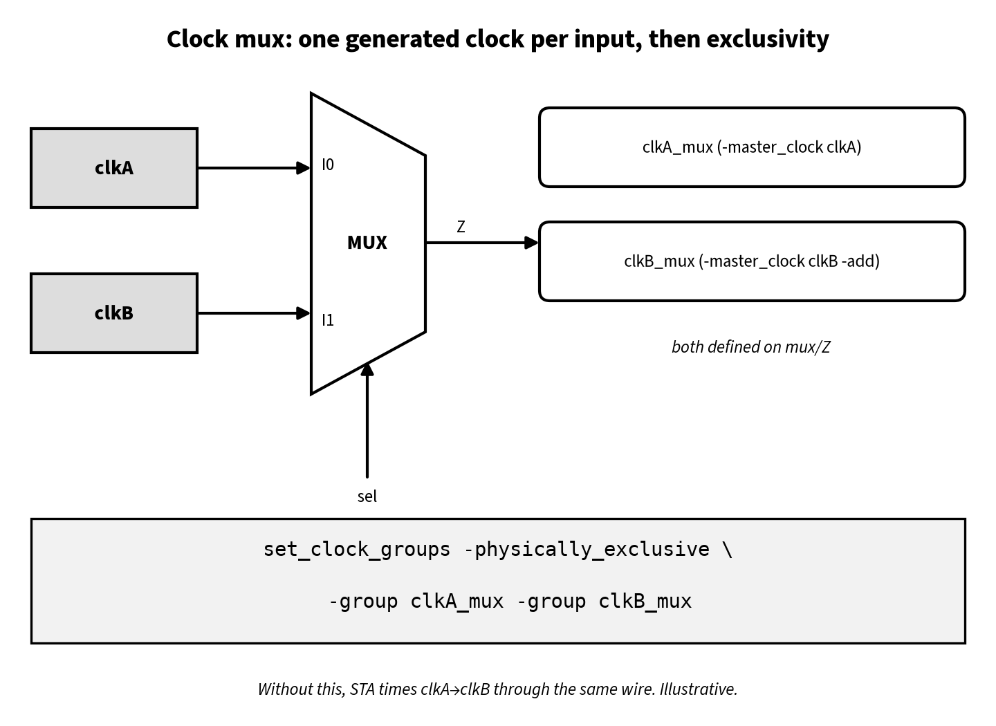
Key points:
-addis required for the second clock. Without it, the second definition replaces the first.-master_clockremoves the ambiguity when more than one clock can reach the-sourcepin.- Physically exclusive means the two clocks can never exist on that net at the same time, so STA should not time them against each other or compute crosstalk between them. Upstream of the mux, keep
clkAandclkB‘s own relationships intact. - Case analysis is the alternative. For a mode-specific STA run you can
set_case_analysison the select pin and analyse one clock at a time. That is simpler but needs one mode per select value.
PLLs and dividers by one
A PLL output can be modelled as a generated clock from the reference input with -multiply_by (and -duty_cycle if needed), or as a fresh create_clock at the PLL output when the PLL is treated as a black box and the reference relationship doesn’t matter for timing. Which one to use depends on whether paths cross between reference and output domains and how feedback compensation is modelled; follow the PLL IP’s integration notes.
-divide_by 1 with -combinational is useful when you want a new clock name at a point such as a clock output port or a mux output, keeping the master waveform. With -combinational, the source latency follows only the combinational path from master to target. It won’t jump through sequential elements, latch data pins or other generated clock sources.
Clock gating cells do not need generated clocks. The clock propagates through an ICG’s clock arc, and the enable path gets a clock-gating check. See Clock Gating and ICG.
CTS and physical design implications
Generated clocks also shape the clock tree:
- Balancing through the divider. If synchronous paths cross between
CLKandclk_div2, the generated clock’s sinks usually have to be balanced against the master’s sinks. Example A shows the skew if this is ignored. See Clock Tree Synthesis (CTS) and the CTS spec file. - OCV and CRPR. The common clock path between master and generated domains runs up to the point where the divider branch leaves the master tree. CRPR credit applies only to that shared segment. See OCV, AOCV and POCV in STA.
- ECOs. Resizing the divider flop or rebuffering its output changes the generated clock’s source latency for every sink downstream. Re-run hold on the crossing paths after such ECOs. See ECO in VLSI Physical Design.
Debug flowchart: when generated-clock timing looks wrong
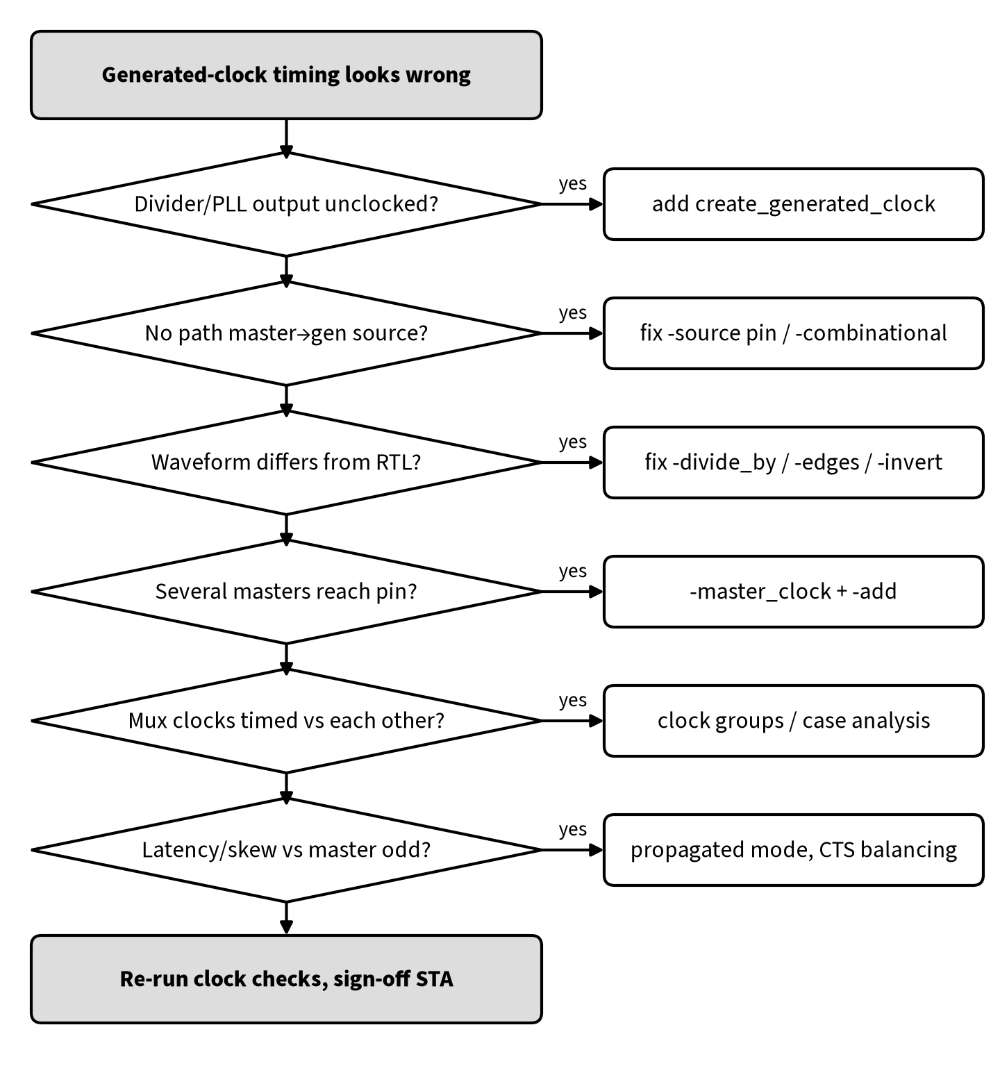
Practical habits that catch most problems before they reach sign-off:
- Run the tool’s clock lint first. The
check_timing-style report lists unclocked registers, unconstrained endpoints and generated clocks with no path to their master. Treat its warnings as errors. - Read the clock report. Check that every generated clock shows the expected master, period, waveform and source pin.
- Report one crossing path in full. In propagated mode the generated clock’s arrival should include the divider CK→Q.
- Look for duplicate definitions. Two clocks on the same pin without
-addmeans one replaced the other. Two clocks with-addand no exclusivity means STA is timing them against each other. - Compare ideal and propagated runs. Hold violations that appear only post-CTS on master-to-generated crossings usually mean the trees were not balanced through the divider.
Interview Q&As
Q1. What is a generated clock?
A. A clock derived from a master clock (divided, multiplied, edge-selected, shifted or inverted), declared with create_generated_clock at an internal pin. It inherits the master’s edge relationship and gets source latency from the master source to its definition point.
Q2. Why can’t you just use create_clock on a divider’s Q pin?
A. That creates an independent clock starting at time 0 at the Q pin. It loses the source latency through the master tree and divider CK→Q, and the edge alignment to the master. Crossing paths get wrong skew, and hold violations can be hidden.
Q3. Why doesn’t the master clock propagate to the divider output automatically?
A. STA propagates clocks through combinational arcs only, not through a sequential cell’s CK→Q arc. The Q pin is a data output unless you define a clock on it.
Q4. Write the SDC for a divide-by-2 on div_reg/Q.
A. create_generated_clock -name clk_div2 -source [get_pins div_reg/CK] -divide_by 2 [get_pins div_reg/Q], or equivalently with -edges {1 3 5}.
Q5. Give a 50% duty divide-by-3 with -edges.
A. -edges {1 4 7}: rise on edge 1, fall on edge 4 (1.5 master periods later), next rise on edge 7 (3 periods).
Q6. What do -master_clock and -add do?
A. -master_clock picks which clock is the master when several reach the -source pin. -add lets you put another clock on a pin that already has one, instead of overwriting it.
Q7. How do you constrain a clock mux?
A. Define one generated clock per input on the mux output (-master_clock, -add), then use set_clock_groups -physically_exclusive. Or use case analysis on the select pin, one mode per run.
Q8. Physically vs logically exclusive clocks?
A. Physically exclusive clocks can never coexist on the same net (for example, two clocks on one mux output). Logically exclusive clocks exist physically but are never active together because of mode logic. Physically exclusive also tells the tool not to compute crosstalk between them.
Q9. Master-to-generated crossing fails hold only after CTS. Why?
A. The generated clock’s sinks see the master tree plus the divider CK→Q plus the generated tree, so they arrive later than the master sinks. That skew hurts hold on master→generated paths. Balance the trees through the divider, or fix hold.
Q10. Should a divided clock be async to its master?
A. No. It is synchronous by construction, and real paths between them should be timed, with multicycle paths where the RTL guarantees them. Async grouping is for unrelated clocks with synchronisers.
FAQ
Does every divider need a generated clock?
Every divider whose output is used as a clock does. If the divided signal is only used as data (an enable, for example), it is not a clock, and the downstream flops stay on the master clock with a multicycle path where appropriate.
How do generated clocks interact with OCV?
The divider’s CK→Q delay and the generated tree are clock-path delays, so they get early/late derates. CRPR only credits the segment shared with the master. See OCV, AOCV and POCV in STA.
Summary
- A generated clock is derived from a master clock and declared with
create_generated_clockat the internal pin where the waveform appears. - STA cannot infer divided clocks because clocks don’t propagate through CK→Q arcs. Undeclared dividers leave flops unclocked.
- Describe the real waveform with
-divide_by,-multiply_by,-edges,-edge_shiftand-invert. Edges are numbered from 1, odd for rising and even for falling. - Generated clocks carry source latency through the master tree and the divider. A stray
create_clockdrops it and can hide hold violations. - Master and generated domains are synchronous: time their crossings, and add multicycle paths only when the RTL guarantees them.
- For muxes, use one generated clock per input with
-master_clock/-addplus physical exclusivity, or case analysis. - In PD, balance the trees through the divider, place dividers near the root, and re-check hold after ECOs that touch the divider.