
Routing turns the logical connections of a placed, clock-tree-built design into real metal wires and vias. It is the last big implementation step before sign-off, and it is where problems hidden earlier in the flow finally show up: a congested region that placement could not spread, a pin that no wire can reach, a long net that looked fine with estimated parasitics but fails setup once real RC and coupling are extracted.
This guide covers pre-route checks, metal layers and vias, global routing, track assignment, detailed routing, NDRs, post-route optimization, QoR checks, a debug flowchart and interview Q&As. Worked examples are illustrative: the numbers show the method and do not come from any foundry, library or project unless an open-source flow is named. Commands follow the open-source OpenROAD tools because their documentation is public; commercial tools have equivalent steps under other names. Related reading on iVLSI: Placement in VLSI, Clock Tree Synthesis (CTS), Routing Congestion in VLSI and Crosstalk in VLSI.
What is routing in VLSI?
Routing is the physical design step that creates the metal geometry for every net in the design so that each driver pin is electrically connected to all of its load pins. It runs after placement and clock tree synthesis, and its output feeds parasitic extraction, sign-off timing and physical verification.
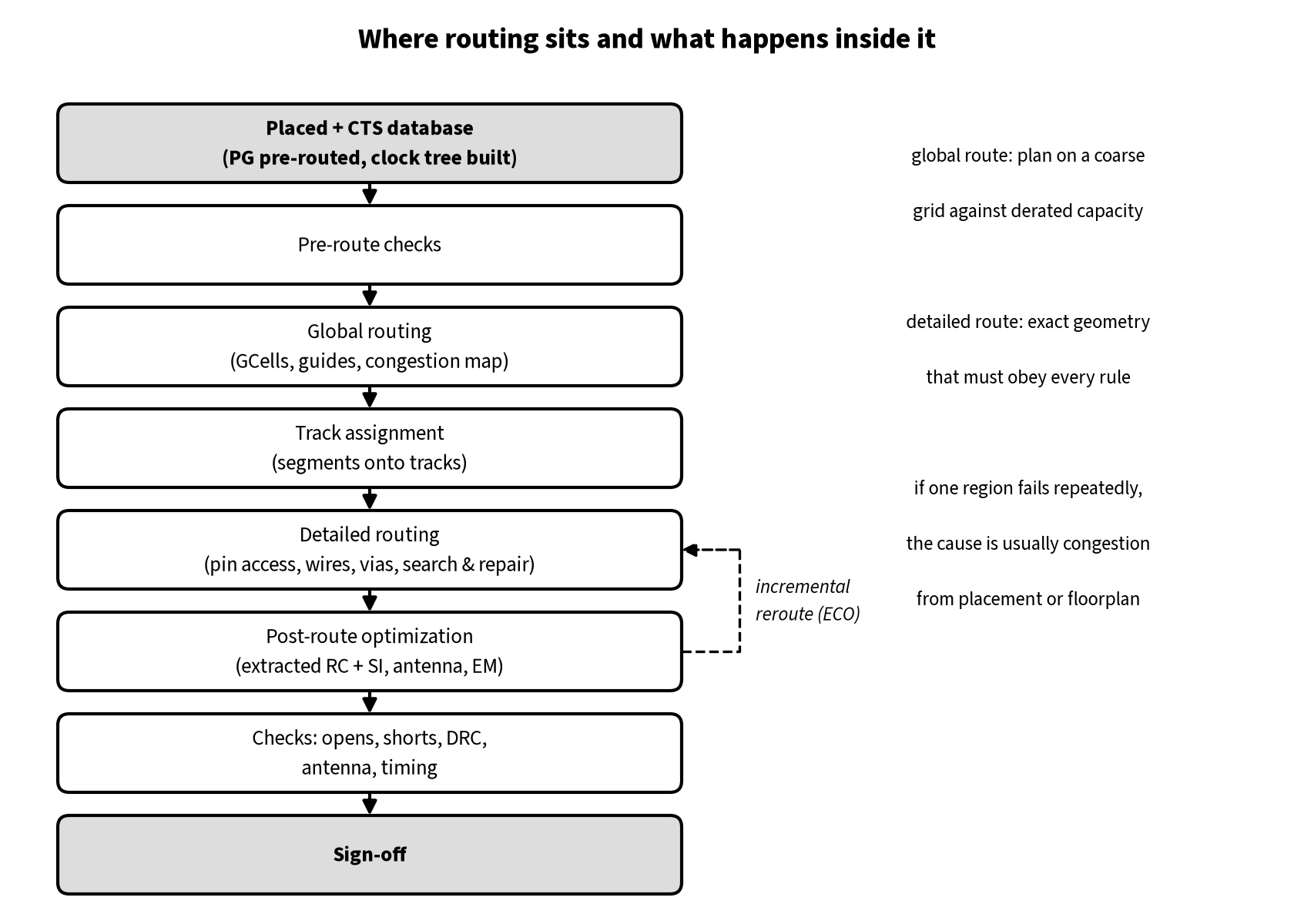
There are three kinds of routing in a typical block flow:
- Power/ground (PG) routing. Rings, stripes and standard-cell rails are built during floorplanning and power planning (see Power Planning in VLSI). The signal router treats them as fixed obstacles.
- Clock routing. After CTS inserts the clock buffers, clock nets are routed, usually with stricter rules (wider wires, extra spacing, sometimes shielding) and on a chosen range of layers. Many flows route clock nets first so they get the best resources.
- Signal routing. All remaining data, scan, reset and control nets are routed in the routing stage proper.
The goals of signal routing are completion (no opens or shorts), design-rule cleanliness (see Technology DRCs in VLSI), timing with real wire RC and crosstalk, signal integrity and reliability (noise, antenna, electromigration), and manufacturability (fewer single-cut vias and jogs).
Inputs and pre-route checks
The router reads the post-CTS database, the technology LEF (layers, directions, pitches, spacing tables, vias), cell LEFs (pins and obstructions), timing libraries, the SDC and special rules such as non-default rules (NDRs), routing blockages and layer limits.
Before routing, most teams check that:
- Placement is legal and the clock tree is built, with clock NDRs applied where needed.
- Congestion is acceptable. A congested design will not route cleanly by itself; fix hotspots at placement or floorplan level first (see Routing Congestion in VLSI).
- Timing and DRVs are within reach. Routing adds RC and coupling, so slack only gets worse (see DRVs in VLSI).
- Constants are tied off through tie cells, and the PG grid and power intent are clean.
Metal layers, preferred directions, tracks and vias
A modern process has many metal layers. Lower layers are thin with a tight pitch: they give many tracks for short local connections but have high resistance per micron. Upper layers are thicker and wider: fewer tracks, much lower resistance, used for long nets, clocks and power. The exact stack, pitches and resistances come from your foundry’s technology files.
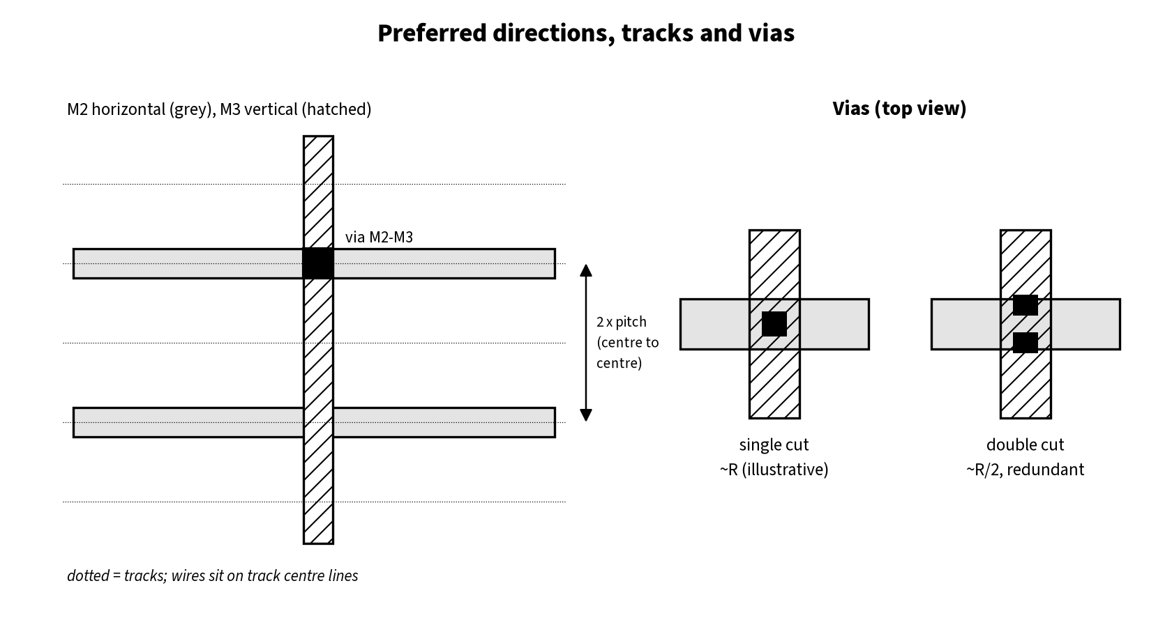
Each routing layer has a preferred direction, and adjacent layers usually alternate horizontal and vertical. Wires run on tracks, which are the legal centre lines on a layer, spaced at the layer’s pitch (centre-to-centre distance). Spacing is the edge-to-edge gap between wires, and the offset places the first track. Wrong-way routing is restricted or banned on many layers and always costs tracks.
A via connects wires on two adjacent metal layers through the dielectric between them; a stack of vias connects non-adjacent layers. A single-cut via has one cut; a multi-cut or redundant via has two or more cuts in parallel, which lowers resistance and keeps the connection alive if one cut is defective. Routers typically add redundant vias in a later DFM step wherever there is room.
Which layers a net can use
The flow tells the router which layer range signals and clocks may use. In OpenROAD this is set_routing_layers, for example set_routing_layers -signal Metal2-Metal10 -clock Metal6-Metal9 from the tool’s documentation. The open-source OpenROAD-flow-scripts (ORFS) platform for the public Nangate45 library sets MIN_ROUTING_LAYER = metal2, MIN_CLK_ROUTING_LAYER = metal4 and MAX_ROUTING_LAYER = metal10, so clocks are kept off the two lowest signal layers.
Worked example A: why long nets are promoted to upper layers (illustrative)
Take a 200 µm net driven by a gate with an effective drive resistance of 1 kΩ into a 2 fF load. Assume two candidate layers with the same capacitance, 0.2 fF/µm, but different resistance: a lower layer at 2 Ω/µm and an upper layer at 0.4 Ω/µm. Using the Elmore approximation for a distributed RC wire, delay ≈ R_drv × (C_wire + C_load) + R_wire × (C_wire / 2 + C_load).
- C_wire = 200 × 0.2 = 40 fF on both layers, so the driver term is 1 kΩ × 42 fF = 42 ps in both cases.
- Lower layer: R_wire = 400 Ω, wire term = 400 Ω × (20 + 2) fF = 8.8 ps. Total ≈ 50.8 ps.
- Upper layer: R_wire = 80 Ω, wire term = 80 Ω × 22 fF = 1.76 ps. Total ≈ 43.8 ps.
Promotion cuts the wire’s own delay by 5×, and that term grows with length squared, so long nets gain most. Here the driver term still dominates, so upsizing may help as much, and the via stacks at each end make promotion pointless for short nets. Real values come from your extraction rules; see Parasitic Extraction and SPEF in VLSI.
Stage 1: Global routing
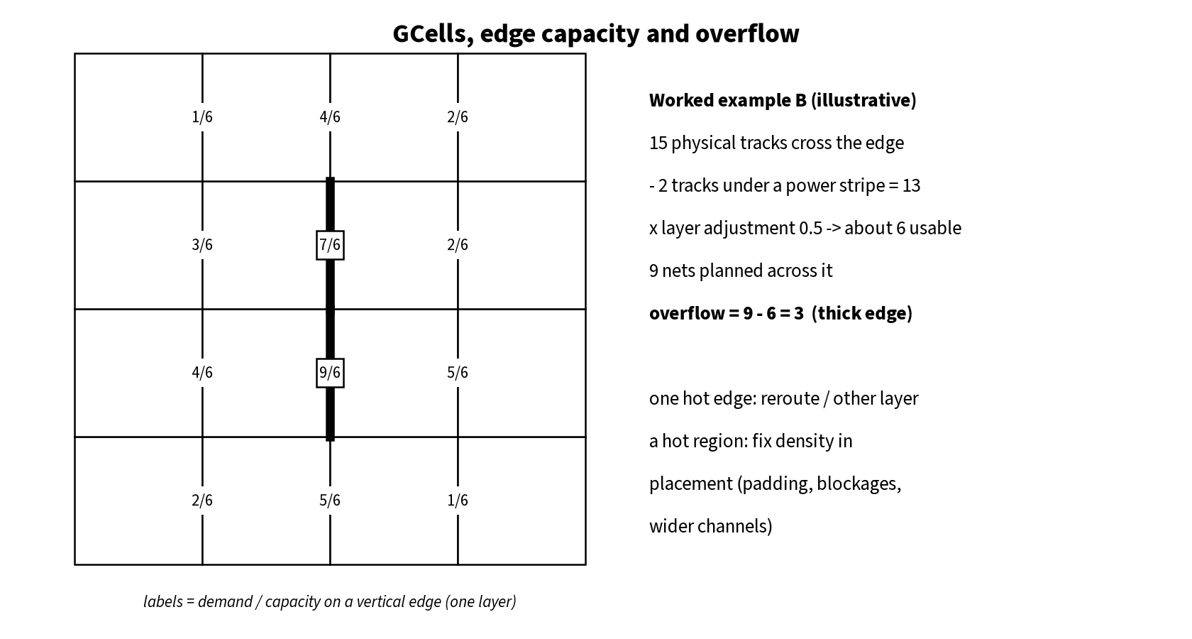
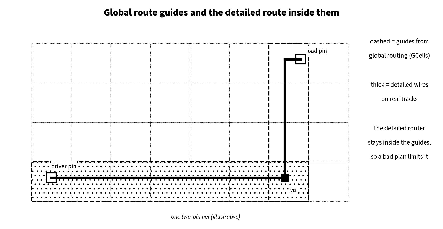
Global routing divides the routing area into a grid of rectangular tiles called GCells (global routing cells; some tools say GRCs or bins). For each GCell boundary and each layer, the router knows the capacity: how many tracks cross that edge after subtracting blockages, PG wires and pre-routes. It then plans each net as a path through GCells, not through exact tracks.
The output is a set of route guides, one rectangle per GCell region a net passes through on each layer, plus a congestion map. The OpenROAD global router (grt) is based on FastRoute, and its documentation notes that the default GCell size is 15 M3 pitches. global_route writes guides with -guide_file, runs up to -congestion_iterations rip-up-and-reroute passes (default 50 for FastRoute) to remove overflow, and can give timing-critical nets priority with -critical_nets_percentage.
Capacity, demand and overflow
Demand is the number of nets the global router has sent across an edge. When demand exceeds capacity the edge overflows, and overflowed edges are where detailed routing will struggle or fail. Global routers also apply layer adjustment (derating): they deliberately assume fewer tracks than really exist, because detailed routing loses tracks to pin access, vias and spacing rules. In OpenROAD, set_global_routing_layer_adjustment Metal4 0.5 reduces Metal4’s capacity by 50% for the global router; the ORFS Nangate45 platform applies 0.5 on metal2–metal3 and 0.25 on metal4 and above. Per the ORFS documentation, higher values ease detailed routing but risk detours; lower values can leave detailed routing too little room.
Worked example B: reading GCell overflow (illustrative)
A vertical GCell edge on a horizontal layer has 15 physical tracks. Two tracks are blocked by a power stripe, leaving 13. With a layer adjustment of 0.5 the global router plans against about 6 usable tracks (tools round differently). The router sends 9 nets across the edge, so the edge has an overflow of 3 on that layer.
If neighbouring GCells have spare capacity, more congestion iterations or another layer assignment usually clear it. If a whole region overflows, the problem is cell or pin density and the fix is in placement: padding, lower local density, a partial blockage or a wider macro channel. A clean global route only means the plan fits the derated capacity; it does not guarantee a clean detailed route.
Timing during and after global routing
Global routes give far better parasitic estimates than placement does. In ORFS, after global_route it estimates parasitics from the global routes, runs repair_design and repair_timing, legalizes the changed cells and re-routes only the modified nets incrementally (global_route -start_incremental / -end_incremental).
Stage 2: Track assignment
Track assignment takes each net’s global route and assigns its long segments to specific tracks inside the guides, preferring long straight runs and fewer vias. It is fast but leaves rule violations for the next stage. In TritonRoute, the detailed router used by OpenROAD, the building blocks listed in its documentation are pin access analysis, track assignment, initial detailed routing, search and repair, and a DRC engine.
Stage 3: Detailed routing
Detailed routing creates the final wires and vias on tracks and makes every connection, including the short, awkward ones into cell pins. It works region by region (often called switch boxes or routing windows) and follows the global guides, so a bad global plan limits it.
Its main sub-steps:
- Pin access. For each cell pin, find legal access points and via positions that do not break rules with neighbouring pins or cell obstructions. At advanced nodes this is often the hardest part. OpenROAD runs
pin_accessbefore global routing in ORFS, and options such as-via_in_pin_bottom_layerand-via_in_pin_top_layercontrol where vias may be dropped inside pins. - Initial detailed route. Route all nets inside their guides, accepting some violations.
- Search and repair. Repeatedly find DRC violations (shorts, spacing, end-of-line, minimum area and so on), rip up and reroute the nets in a small window with higher cost on the violating resources, until the count stops dropping. OpenROAD’s
detailed_routehas-droute_end_iterto limit the number of iterations (ORFS defaults to 64) and writes the remaining violations with-output_drc.
What makes detailed routing hard
Pin-dense cells packed together, narrow macro channels, wide NDR nets and advanced-node rules such as end-of-line spacing and multi-patterning coloring (see Double Patterning in VLSI) all cut usable capacity. If the global plan was already overflowed, search and repair cannot invent tracks.
Non-default rules, shielding and special nets
A non-default rule (NDR) overrides the default width and spacing for selected nets. Clock nets commonly use double width (lower resistance and better EM margin) and double spacing (less coupling); some designs also add shielding, routing grounded wires on one or both sides of a sensitive net to block crosstalk. Both cost routing tracks, so they are applied to clocks and to a short list of critical or noise-sensitive nets, not to everything.
Post-route optimization
After detailed routing the tool extracts parasitics from real geometry, including coupling capacitance, and re-times the design. Typical findings and fixes:
- Setup violations from detours, wire RC and crosstalk delta delay: upsize or buffer, swap to a faster threshold voltage, promote the net to an upper layer, or reroute with more spacing.
- Hold violations: insert delay cells where there is room, without damaging setup.
- Crosstalk noise and delta delay: spacing, shielding, upsizing the victim driver or downsizing the aggressor (see Crosstalk in VLSI).
- Antenna violations: long wires on a lower layer connected to a gate collect charge during fabrication. Fixes are layer jumping (break the wire with a jump to a higher layer near the gate) or an antenna diode (see Antenna Effect in VLSI). OpenROAD’s
repair_antennasinserts jumpers and diodes after global routing, andcheck_antennasreports the remaining violations; ORFS loops repair and detailed routing up toMAX_REPAIR_ANTENNAS_ITER_DRTtimes (default 5). - Electromigration: widen wires or add vias on high-current nets (see Electromigration in VLSI and Via Pillars).
Each change is followed by an incremental (ECO) reroute of the touched nets. Late changes go through the ECO flow.
Worked example C: what redundant vias do to resistance (illustrative)
Assume one via cut between two layers has 10 Ω. A two-cut via has the two cuts in parallel, so about 5 Ω, and if one cut is defective the connection still works at about 10 Ω instead of failing open. A net that climbs from metal 2 to metal 6 at the driver and drops back at the load crosses 8 via levels. With single cuts that is about 80 Ω of via resistance; with double cuts about 40 Ω. That is comparable to the wire resistance of a short net (compare worked example A), so redundant vias help timing and EM as well as yield. Real cut resistances come only from your own kit.
Routing QoR: what to check before sign-off
| Check | What “good” looks like | Why |
|---|---|---|
| Opens and unrouted nets | Zero | An unrouted net is a functional failure. |
| Shorts | Zero | Shorts between signals, or to PG, are fatal and also break LVS. |
| Router DRC count | Zero, or a short list understood and planned for manual fixing | Router rules are a subset of the sign-off deck; leftovers only grow. |
| Antenna | Zero after repair | Gate-oxide damage risk in fabrication. |
| Setup / hold with extracted RC and SI | Met in all required corners and modes | Pre-route estimates are only approximations. |
| Transition / capacitance | Within limits | Long detoured nets often break max transition. |
| Wirelength and detours | Close to the global-route estimate; few large detours | Large detours point at congestion. report_wire_length and report_net_detours help in OpenROAD. |
| Redundant via rate | As high as the flow allows | Yield and EM. |
After the router’s own checks, the database goes to sign-off: full-chip RC extraction, sign-off STA, physical verification (DRC and LVS), IR drop and EM analysis, and metal fill.
Common routing problems and fixes
- Thousands of DRCs in one area: almost always congestion or pin access. Check the congestion map there and fix density (padding, partial blockages, wider channels); rerouting harder rarely helps.
- DRCs on one cell type: pin access. Pad that cell, use another variant, or check the via-in-pin layer settings.
- Setup broke after routing: compare pre- and post-route path reports for detours, resistive layers or delta delay; fix with layer promotion, buffering or NDR spacing.
- Router does not converge: the violation count plateaus. Stop, find where violations cluster and fix the cause upstream.
Debug flowchart for routing problems
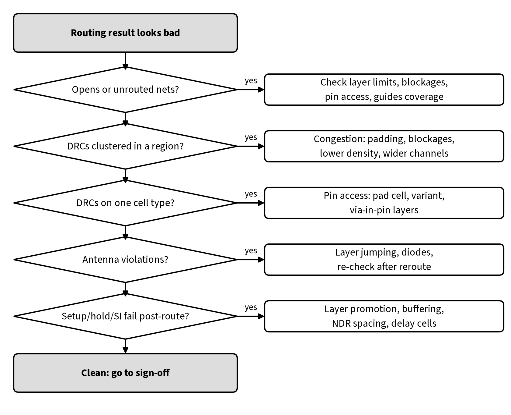
Work top to bottom: completion first, then shorts and DRCs, then antenna, then timing. Every timing fix needs another incremental route and DRC pass.
Interview questions and answers
Q1. What are the stages of routing?
Global routing (GCell-level plan, guides, congestion map), track assignment, and detailed routing (pin access, exact wires and vias, search and repair). Post-route optimization follows.
Q2. What is a GCell and what is overflow?
A GCell is a tile of the global routing grid. Each GCell edge has a capacity in tracks per layer. Overflow is demand above capacity on an edge; overflowed regions are where detailed routing will fail.
Q3. Why do global routers derate layer capacity?
Because detailed routing loses tracks to pin access, vias and spacing rules. Planning against fewer tracks spreads routes and leaves room for detailed routing.
Q4. Why are clock nets routed with NDRs?
Wider wires lower resistance and improve EM margin; extra spacing or shielding cuts crosstalk on nets that switch every cycle and set the timing reference for every flop.
Q5. What is the advantage of a multi-cut via?
Lower resistance (cuts in parallel) and redundancy: if one cut fails, the connection survives. That improves timing, EM and yield.
Q6. Setup failed after detailed routing but passed after placement. Why?
Real RC replaces estimates; nets may detour or land on resistive layers; crosstalk delta delay is now included. Compare the path before and after routing to find which.
Q7. How do you fix antenna violations?
Layer jumping near the gate, adding an antenna diode, or splitting long low-layer wires. Fix after routing and re-check.
For more short-answer practice, see our routing interview questions.
FAQ
Is routing done before or after CTS?
After. Clock nets are routed once the clock tree exists, and signal routing follows. Global routing is often run earlier in a lightweight mode to estimate congestion and parasitics.
Does a clean router mean the design is DRC clean?
Not necessarily. The router checks the rules it knows from the tech LEF; the sign-off DRC deck has more rules. Always run sign-off DRC.
How many metal layers does a chip have?
It depends on the process and the chosen metal stack; read it from your technology files. In the open-source ORFS Nangate45 platform, signals route on metal2 to metal10.
Summary
Routing connects every net with real metal and vias. Global routing plans nets through a grid of GCells against derated capacity and reports congestion; track assignment puts segments on tracks; detailed routing handles pin access, makes exact wires and repairs DRCs. After routing, re-time with extracted RC and crosstalk, fix setup, hold, antenna and EM with incremental reroutes, and judge the result on completion, shorts, DRCs, antenna and timing together. When routing fails in one area, look for the cause in congestion, placement or the floorplan rather than asking the router to try harder.
References
- OpenROAD global routing (
grt) documentation: FastRoute basis,global_routeoptions (-guide_file,-congestion_iterationsdefault 50,-critical_nets_percentage, incremental mode),set_routing_layers,set_global_routing_layer_adjustment,set_macro_extension(default GCell size 15 M3 pitches),repair_antennas,report_wire_length,report_net_detours,report_congestion: https://github.com/The-OpenROAD-Project/OpenROAD/blob/master/openroad/grt/README.md - OpenROAD detailed routing (
drt, TritonRoute) documentation: pin access, track assignment, initial detailed routing, search and repair, DRC engine;detailed_routeandpin_accessoptions: https://github.com/The-OpenROAD-Project/OpenROAD/blob/master/openroad/drt/README.md - OpenROAD antenna checker (
ant) documentation,check_antennas: https://github.com/The-OpenROAD-Project/OpenROAD/blob/master/openroad/ant/README.md - OpenROAD-flow-scripts
flow/scripts/global_route.tcl,detail_route.tcl,variables.yaml(ROUTING_LAYER_ADJUSTMENT,DETAILED_ROUTE_END_ITERATION,MAX_REPAIR_ANTENNAS_ITER_DRT) and the Nangate45 platformconfig.mkandfastroute.tcl: https://github.com/The-OpenROAD-Project/OpenROAD-flow-scripts - M. Pan, Y. Xu, Y. Zhang and C. Chu, “FastRoute: An Efficient and High-Quality Global Router,” VLSI Design, 2012, Article ID 608362: https://onlinelibrary.wiley.com/doi/10.1155/2012/608362
- A. B. Kahng, L. Wang and B. Xu, “TritonRoute: The Open Source Detailed Router,” IEEE TCAD, 2020, doi:10.1109/TCAD.2020.3003234.