
At advanced nodes, the wire is often slower than the gate driving it. The lowest metal layers are very thin and narrow, and their resistance per micron has grown fast with each node. Vias between those layers are tiny and resistive too. A strong cell driving a long net can lose much of its strength in the first few microns, simply climbing from its output pin up to the routing layer that carries the net. Via pillars (Cadence’s term) or via ladders (Synopsys’s term) attack exactly that problem: they build a stack of multiple, parallel vias and short wide metal segments directly above a pin, so the current has a low-resistance path up to the higher, faster layers.
Via pillars serve two purposes: timing (lower resistance on critical nets) and electromigration (EM) (spreading high current over more vias on high-drive pins). This guide explains how they work, when to insert them, what they cost, how to judge whether they help, and the questions that come up in interviews.
Commands and option names below are given in general terms. Option names change between tool versions, so always check the current documentation for Innovus or Fusion Compiler/ICC2.
The problem: resistance near the pin
Think of a net as three parts:
- the pin access part: from the cell’s output pin (on a very low layer) up through the first vias;
- the trunk: the long route on a mid or upper layer;
- the sink access part at each receiver.
On older nodes, the trunk dominated. At advanced nodes, low-layer metal and via resistance has grown so much that the pin-access part can be a meaningful fraction of the total resistance of a short or medium net. A single via at each layer change is a small, resistive bottleneck sitting right where all of the driver’s current flows.
Upsizing the driver does not fix this; a stronger driver pushes more current into the same bottleneck. Using a higher-layer route for the trunk helps the trunk but still forces the current to climb through the narrow via stack. That is why tools introduced a dedicated structure for the climb.
What a via pillar is
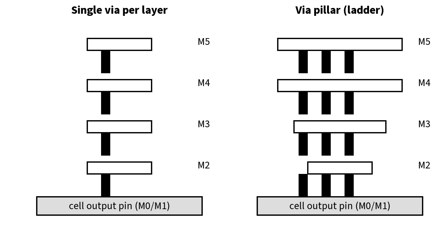
A via pillar is a predefined stack, defined per library pin, made of:
- multiple vias in parallel at each layer transition (for example a 1×2 or 2×2 array),
- short, wider metal segments on each intermediate layer,
- going from the pin layer up to a target layer.
The pillar is defined as a rule (Innovus uses stack-via rules, often in LEF, associated to cell pins; ICC2/Fusion Compiler uses via-ladder rules in the tech file or created with Tcl). Usually the library vendor supplies a list of allowed pillars per pin. The router then implements the pillar on the actual pin and routes the net from the top of the pillar.
Two flavours matter:
- EM pillars / EM via ladders are required on certain high-drive pins to meet current-density limits. They are not optional.
- Performance pillars / performance via ladders are optional, inserted by optimization on timing-critical nets because they reduce resistance.
Worked example (illustrative)
All values are made up for teaching.
Say a driver output must climb from M1 to M5 for its trunk. Assume each single via has 20 Ω and each short M2–M4 segment adds 5 Ω.
- Single-via stack: 4 vias × 20 Ω + 3 segments × 5 Ω = 95 Ω.
- 2-via pillar: vias in parallel give 10 Ω per transition: 4 × 10 Ω = 40 Ω; wider segments, say 3 Ω each: 9 Ω. Total 49 Ω.
If the rest of the net (trunk + sink access) is 300 Ω with 20 fF total load, the Elmore-style delay contribution of the climb, which sees the whole downstream load, is roughly:
- single vias: 95 Ω × 20 fF ≈ 1.9 ps
- pillar: 49 Ω × 20 fF ≈ 1.0 ps
About 1 ps on this net. That sounds small, and on many nets it is — which is exactly the point: pillars help most on nets where the pin-access resistance is a large fraction of the total, such as high-fanout clock drivers, short nets with big loads, and nets driven by very strong cells. On a long net dominated by trunk resistance, the gain is negligible. The pillar also adds a bit of capacitance (more metal, more vias), so on a lightly loaded net it can even hurt. This is why the tool should make the choice from timing, not from a blanket rule.
When to insert pillars in the flow
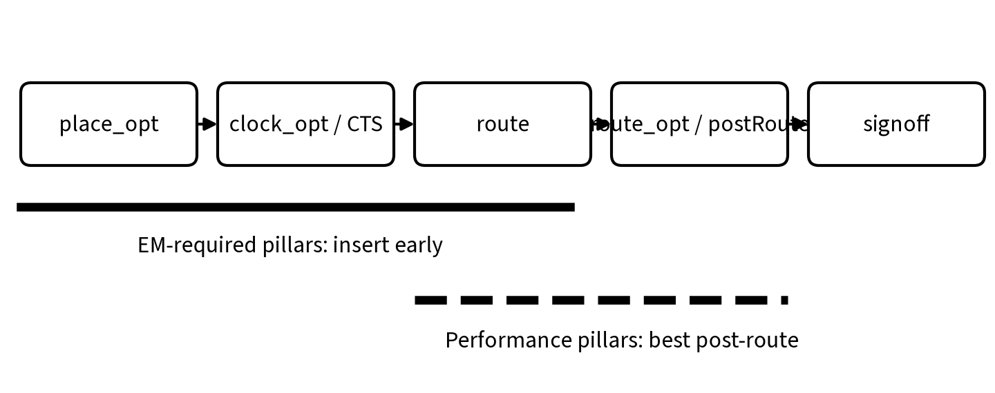
EM-required pillars: early. If the library says a pin requires an EM pillar, the requirement must be honoured from placement onwards. The pillar takes space on several layers, and if it is added late it can collide with existing routes and pin access. Cadence’s guidance (as reproduced in the publicly circulated “Via Pillar Flow in Innovus” application note) is that when EM pillars are required, via-pillar optimization should start from the place_opt_design stage.
Performance pillars: late, usually post-route. Before routing, the tool cannot know the real parasitics of the climb, so it is hard to predict whether a pillar is worth it. The same application note recommends starting optional via-pillar optimization post-route when EM pillars aren’t required, for more stable timing gains. In Synopsys flows, performance via-ladder insertion is controlled by an application option and happens during optimization steps such as place_opt, clock_opt final optimization and route_opt; check the current documentation for exact options and defaults.
Clock nets: after CTS, before clock routing. Clock drivers are high-drive and often need EM pillars. Insert them after the tree is built and before clock routes are committed.
The costs
Via pillars are not free.
- Routing resources: a pillar occupies tracks on several layers above the pin. In a dense area, that blocks neighbouring nets and can create detours.
- Pin access: pillars on one cell can block access to neighbours’ pins, especially in high-density cell rows. See our congestion guide.
- Placement: some flows reserve space or enforce spacing around pillar cells, which reduces effective utilization.
- Capacitance: extra metal adds capacitance, so the benefit must be judged with real extraction.
- DRC risk: stacked vias and wide short segments have their own rules (minimum area, enclosure, cut spacing). Late insertion often produces DRCs.
How to tell if pillars are helping
- Compare before/after on the same paths. Report the stage delay of the driver and the net, not only path slack, because other optimizations may have changed at the same time.
- Use signoff extraction. Pre-route estimates of pillar benefit can be wrong. Judge with post-route parasitics.
- Check congestion and DRC maps around the pillars you added.
- Count them. If the tool added pillars on thousands of non-critical nets, you are paying routing cost for nothing; restrict insertion to critical nets.
- For EM pillars, check the EM report to confirm the pin current density violations are gone.
A decision flow
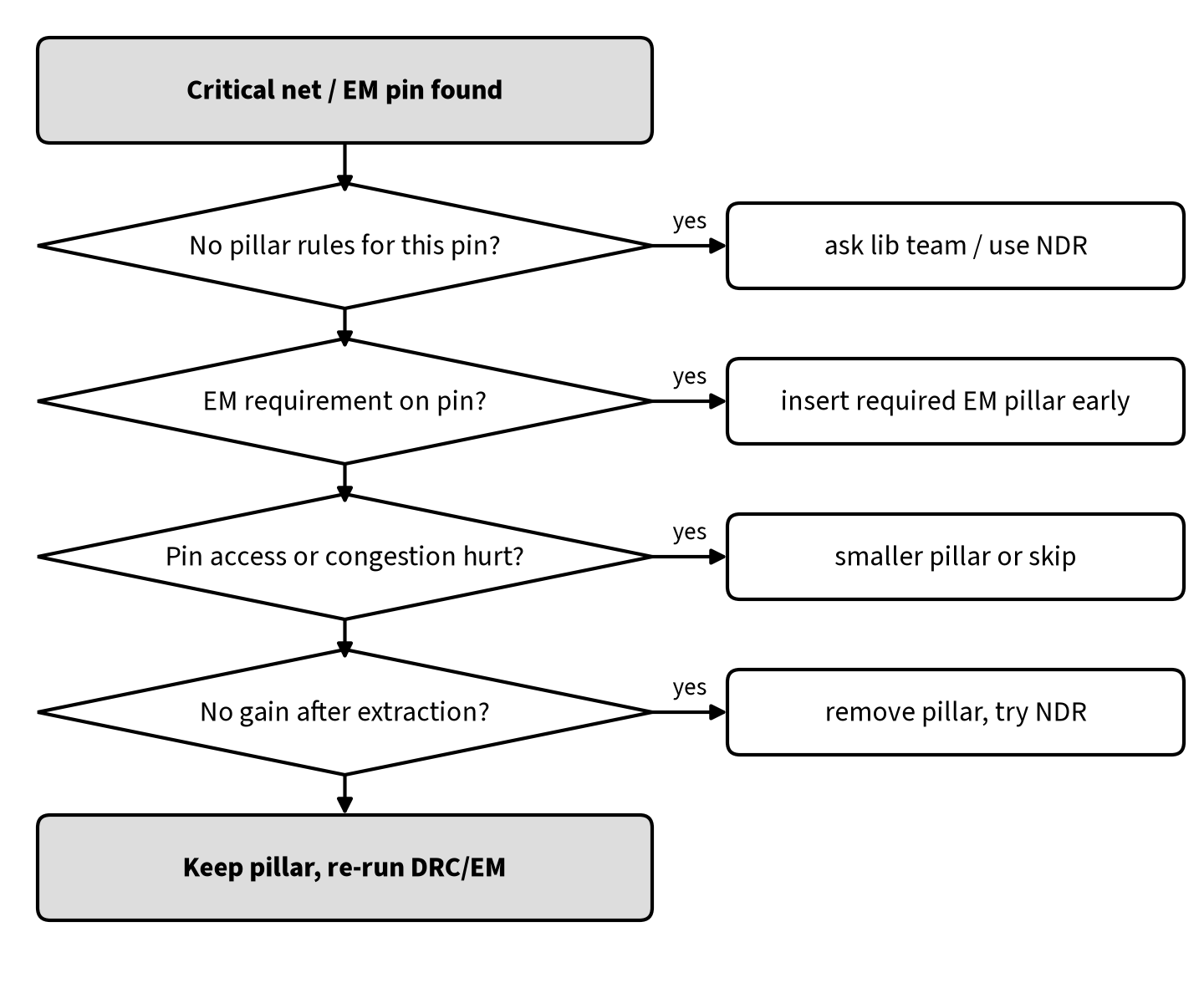
- Is there a pillar rule for this pin in the library? If not, ask the library team; meanwhile use NDRs (wider wires, double vias) or upsizing.
- Does the pin have an EM requirement? If yes, insert the required pillar early and keep it.
- Is the area congested, or would the pillar block neighbours’ pin access? If yes, choose a smaller pillar or skip it.
- After routing and extraction, did the pillar improve the stage delay? If not, remove it and try other fixes.
- Keep the pillar and re-run DRC and EM checks.
What a pillar check looks like in practice
The listing below is representative only: it shows the kind of information you should pull for a pillar review, not the exact output of any tool.
Net: u_cpu/n_clkdrv_12   Driver: u_cpu/ckbuf_12/Z (CKBUF_X16)
  Pillar rule assigned : VP_2x2_M1_M5   (EM required: yes)
  Pin-access R  (before / after) : 94.8 ohm / 48.6 ohm
  Net cap       (before / after) : 19.6 fF  / 20.3 fF
  Driver stage delay (before / after) : 18.4 ps / 17.2 ps
  EM: peak current density on M1-M2 vias : 1.32x limit -> 0.71x limit
  Local DRCs introduced : 0   Neighbour pin-access warnings : 1
Read it in this order: is the rule the one the library requires, did EM go below the limit, did the stage delay actually improve after extraction, and did the pillar disturb neighbours? A pillar that fixes EM but creates a pin-access warning is still usually kept (EM is mandatory); the neighbour gets fixed by moving or swapping that cell. A performance pillar that gives no delay gain should be removed.
Via pillars vs other low-resistance techniques
| Technique | What it changes | Best for |
|---|---|---|
| Via pillar / ladder | Pin-access climb: multiple vias + wide short metal | Strong drivers, EM pins, short heavily loaded nets |
| NDR (wider/spaced wires) | Trunk resistance and coupling | Long critical nets, clocks |
| Layer promotion | Moves trunk to faster upper layers | Long nets |
| Redundant / double vias | Via yield and some resistance along the route | General reliability |
| Driver upsizing | Drive strength | Nets limited by driver, not wire |
They often combine: a clock driver with an EM pillar, an NDR trunk on upper layers and double vias along the route is a common pattern.
Interview questions and answers
Q1. What is a via pillar?
A predefined stack of parallel vias and short, wide metal segments above a cell pin, giving a low-resistance path from the pin layer to a higher routing layer.
Q2. Why are via pillars needed at advanced nodes?
Low-layer metal and via resistance has grown, so the climb from the pin to the routing layer can be a significant part of net delay and a current-density (EM) risk.
Q3. What is the difference between EM pillars and performance pillars?
EM pillars are required on pins to meet current-density limits; performance pillars are optional and inserted for timing.
Q4. When should performance pillars be inserted?
Usually post-route, when real parasitics are known, unless EM pillars are required, in which case pillar optimization starts at placement.
Q5. What are the downsides of via pillars?
Routing track usage, pin-access blockage, extra capacitance and DRC risk.
Q6. What is the Synopsys equivalent of a via pillar?
A via ladder, defined as a via rule and inserted by EM or performance via-ladder flows.
Q7. Can a via pillar make timing worse?
Yes, on a lightly loaded net its added capacitance can outweigh the resistance saved, and it can cause detours for neighbouring nets.
FAQ
Do I need via pillars on all clock nets?
Not on all of them; typically on high-drive clock drivers with EM requirements and on critical clock trunks. Check your library’s requirements.
Are via pillars the same as stacked vias?
A stacked via is a single via column. A pillar has multiple vias per transition and wider metal, and is defined as a rule per pin.
Who defines pillar rules?
Usually the library vendor or internal library team, based on the technology’s via and metal rules.
How do pillars relate to antenna rules?
They add metal and vias near the pin, so they can affect antenna ratios; run antenna checks as usual. See our antenna effect guide.
Summary
- Via pillars (Cadence) or via ladders (Synopsys) reduce resistance and current density in the pin-access climb.
- EM pillars are mandatory where the library requires them and must go in early; performance pillars are best judged post-route.
- They cost routing tracks, pin access, capacitance and DRC risk, so insert them selectively and verify with real extraction.
- Combine them with NDRs, layer promotion and sizing for critical nets. For the timing basics behind all of this, see our static timing analysis guide.