- Standard design constraints or Synopsys design constraints contains the timing and power related constraints which control design w.r.t to the spec.
- SDC contents:
#Clock definition:
To define clock, we need following four mandatory informations.
1. Clock source: it can be a port of the design or be a pin of a cell inside the design. (typically, that is part of a clock generation logic).
2. Period: the time period of the clock.
3. Duty cycle: the high duration (positive phase) and the low duration (negative phase).
4. Edge times: the times for the rising edge and the falling edge.
create_clock –name <clock_name> -period <Time_period> -waveform {<rise_time> <fall_time>} [get_ports <clock_port_name>]
EG. -> create_clock –name test_clk -period 20 -waveform {0 10} [get_ports clk_pll]
create_clock –name test_clk -period 20 -waveform {10 20} [get_ports clk_pll]
create_clock –name test_clk -period 15 -waveform {5 12} [get_ports clk_pll]
create_clock –name test_clk -period 20 -waveform {0 5 10 15} [get_ports clk_pll]
create_clock -period 1.2 -waveform {0.3 0.4 0.8 1.0} [get_ports clk_pll]
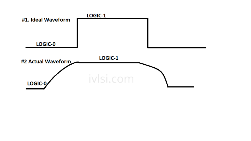
#Setting clock transition:
Set_clock_transition –rise 0.05 [get_clocks test_clock]
Set_clock_transition –fall 0.08 [get_clocks test_clock]

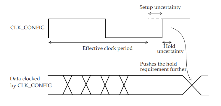
#Clock Uncertainty:
set_clock_uncertainty -setup 0.01 [get_clocks CLK_CONFIG]
set_clock_uncertainty -hold 0.002 [get_clocks CLK_CONFIG]

#Interclock uncertainty:
set_clock_uncertainty -from SYS_CLK -to CFG_CLK -hold 0.05
set_clock_uncertainty -from SYS_CLK -to CFG_CLK -setup 0.1

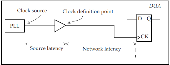
#Clock Latency:
set_clock_latency 1.2 -rise [get_clocks TEST_CLK]
set_clock_latency 1.8 -fall [all_clocks]
set_clock_latency 0.851 -source -min [get_clocks CFG_CLK]
set_clock_latency 1.322 -source -max [get_clocks CFG_CLK]

#Generated Clock:
There are two types of generated clocks:
#1. Divide By Clock
#2. Multiply By Clock
#1. Divide By Clock
create_generated_clock -name TEST_CLK_DIV2 -source TEST_PLL/CLKOUT -divide_by 2 [get_pins UFF0/Q]

#1. Multiply By Clock
create_generated_clock -name PCLKx2 -source [get_ports PCLK] -multiply_by 2 [get_pins UCLKMULTREG/Q]

#Set input delay:
Set Tclk2q 0.5
Set Tc1 0.3
set_input_delay -clock CLKA -max [expr Tclk2q + Tc1] [get_ports INP1]
#Set Output Delay:
Set Tc2 0.5
Set Tsetup 0.3
set_output_delay -clock CLKQ -max [expr Tc2 + Tsetup] [get_ports OUTB]
Modeling of External Attributes, Mostly for IO path we need these attributes.
#set_drive
set_drive -rise 3 [all_inputs]
set_drive -fall 2 [all_inputs]
#set_driving_cell
set_driving_cell -lib_cell INV3 -library slow [get_ports INPB]
#set_input_transition
set_input_transition 0.85 [get_ports INPC]
set_input_transition 0.6 [all_inputs]
#set_load
set_load 5 [get_ports OUTX]
set_load 25 [all_outputs]
Four common commands that are used to constrain the analysis space are:
#set_case_analysis:
Specifies constant value on a pin of a cell, or on an input port.
set_case_analysis 0 [get_ports {testmode[3]}]
#set_disable_timing:
Breaks a timing arc of a cell.
set_disable_timing -from S -to Z [get_cells UMUX0]
#set_false_path:
Specifies paths that are not real which implies that these paths are not checked in STA.
#set_multicycle_path:
Specifies paths that can take longer than one clock cycle.
The site gives a very good knowledge about the library files required for the PD. One doubt is that what is the use of the supply set in the UPF.
Thanks, Rachita for reading the article. Let me explain your doubt. Different power domains present in the design need different supply voltages so before defining the supply voltage for a particular domain we need to create a set of supply so that we can pass it to the power domains. let’s take one example of daily life, if two of your friends are ordering 2 different meals and meals are coming inset of what you order then this won’t confuse both if you but if this doesn’t come in set then it might confuse you. I hope this is clear.
Short and precise info good to start working on writing timing constraints
Thanks Ramesh! We will keep you updated with more informative contents.
Thanks for the info. Very useful for PD freshers.
Thanks Tharun!
Really very good information for the backend fresher. All libs/lef/def and sdc information is the backbone of Physical design.
Thanks for sharing this and can’t wait for upcoming blogs.
Thanks Gaurav! Keep visiting our website for more such useful contents.
Very detailed article.. has a lot of useful information that you cannot find on other Vlsi blogs.
Thanks Malavika! That’s exactly our intention – to provide detailed information about every topic that is not readily available on the internet.
Thanks for sharing such valuable info in one place. Cheers to the Author
Thanks Akaash!
Good Explanation of the basic concepts of PD
Thanks Deepak!
Great information about the required files in PD thanks for the author to present valuable information.
Thanks Jagathi! Keep visiting our website for more such useful contents.
Very good informative blog..! Kudos
Can you please explain in detail Where , when and why do we use don’t_touch and don’t_use Constraints in the design?
Thanks..!
Thanks, Sai. Let me explain both dont_use and dont_touch here (Anyways in later sections I have planned to explain more in detail). Dont_use is the constraint we apply to the many cells which are not coming in the usable range, for example, high drive strength will cause PDN issues, and low drive strength cells are not used for fabrications issues. We do apply this constraint not to use during any stage of the design not even during optimization. Coming to dont_touch we apply this constraint of which we don’t want a tool to do optimization wrt these elements. For example, we fix a few clock elements in the design so that our clock will not get disturbed during optimization otherwise we will have timing variations again which we might need a fix again. I hope this clarifies your doubts.
Thanks
Author
Great work very nicely explained
Thanks Prabhat!
Thanks for explaining & I have seen the comments too. Thanks for very good and valuable info
Thanks Satya! Keep visiting the website and keep learning.
on what basis operating frequency calculated?
Hi Bablu,
The frequency of the design is being calculated based on specification. Please read the physical design flow page for more information. Let me know if you need any further informations. we can talk over those.
Thanks
Gaurav
Thank you
Will you please explain me about .tdf file??
.tdf files contain floorplan-related info from the full chip Team.