
Time borrowing, also called cycle stealing, is a property of latch-based designs in which a slow logic stage is allowed to use part of the time budget of the next stage. It is possible because a level-sensitive latch is transparent for a whole clock phase, instead of sampling data at a single edge like a flip-flop. In this tutorial we cover how time borrowing in VLSI works, how STA tools calculate the borrowed time, the maximum time borrowing limit, a full worked numeric example, the related hold check, and common interview questions.
If you are new to timing checks, first read Static Timing Analysis (STA) in VLSI and Setup and Hold Violations, since time borrowing builds directly on the setup equation.
Flip-Flop vs Latch: Why Borrowing is Possible
A flip-flop is edge-triggered: it samples D only at the active clock edge. Every path between two flip-flops must fit inside one clock period (minus setup and uncertainty). If one stage needs more time and the next stage needs less, the flip-flop cannot share the spare time – the slow stage simply fails.
A latch is level-sensitive. A positive latch is transparent while the clock is high and holds while the clock is low; a negative latch is transparent while the clock is low. While the latch is transparent, any change at D passes to Q after the D-to-Q delay. So if data arrives after the latch opens but before it closes, it is still captured correctly – it just starts the next stage later. That late arrival is the borrowed time.
| Property | Flip-flop | Latch |
|---|---|---|
| Triggering | Edge (rising or falling) | Level (high or low phase) |
| Capture point | Single clock edge | Anywhere in the transparent window (closes at the closing edge) |
| Time borrowing | Not possible | Possible, up to the transparent window minus setup |
| Timing analysis | Simple, each path independent | Paths through latches are coupled across stages |
| Typical usage | Most synchronous logic | High-speed datapaths, ICG cells, lockup latches, some low-power designs |
| Area per bit | Larger (master + slave latch) | Smaller (single latch) |
Key Terms: Opening Edge, Closing Edge and Borrowed Time
- Opening edge – the clock edge at which the latch becomes transparent (rising edge for a positive latch, falling edge for a negative latch).
- Closing edge – the clock edge at which the latch stops being transparent and holds its value.
- Transparent window – the time between the opening and closing edge, i.e. the clock pulse width of that phase.
- Borrowed time – how much later than the opening edge the data arrives at the latch D pin.
- Maximum time borrow – the latest the data can arrive and still meet the latch setup check at the closing edge.
Borrowed time   = Data arrival time at latch D - Opening edge time      (if > 0)
Max time borrow = Closing edge - Opening edge - Tsetup(latch) - clock uncertainty
                = Pulse width - Tsetup - Tunc   (for ideal clocks)
If the arrival is before the opening edge, no time is borrowed: the latch output changes at the opening edge and the next stage starts from there, exactly as with a flip-flop. If the arrival is after the closing edge minus setup, the latch itself has a setup violation – borrowing cannot exceed the window.
Pulse width and duty cycle therefore directly limit borrowing. See Duty Cycle & Pulse Width for how duty-cycle distortion in the clock tree changes the transparent window.
How STA Handles Time Borrowing
STA tools treat a latch D pin in two ways depending on arrival time:
- Arrival before the opening edge – the path ends at the latch with positive slack measured against the opening edge, and the next path starts from the latch clock pin (opening edge).
- Arrival inside the transparent window – the tool reports the path as meeting timing at the latch with the borrowed amount (often with zero slack at the latch, since time is given to the next stage), and the next path starts at the latch D pin, carrying the late arrival forward through the D-to-Q arc.
- Arrival after the closing edge minus setup – a setup violation at the latch.
Because of this, paths through latches are coupled: the slack of the stage after the latch depends on how much the stage before it borrowed. Timing reports for latch paths typically show a “time borrowed from endpoint” line and a separate path that starts at the latch D pin. Most sign-off tools also let you cap borrowing with a constraint (for example set_max_time_borrow in Synopsys-style SDC) so that some margin is kept for the next stage.
Worked Example: Time Borrowing Through a Negative Latch
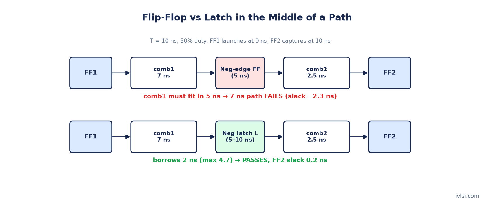
Consider a path FF1 → comb1 → L → comb2 → FF2, where FF1 and FF2 are positive-edge flip-flops and L is a negative latch (transparent while CLK is low). Assumptions, to keep the arithmetic clear:
- Clock period T = 10 ns, 50% duty cycle: rising edges at 0 and 10 ns, falling edge at 5 ns.
- Ideal clock (no skew or uncertainty), zero clock-to-Q and D-to-Q delay.
- Setup time of L and FF2 = 0.3 ns.
- comb1 = 7 ns, comb2 = 2.5 ns.
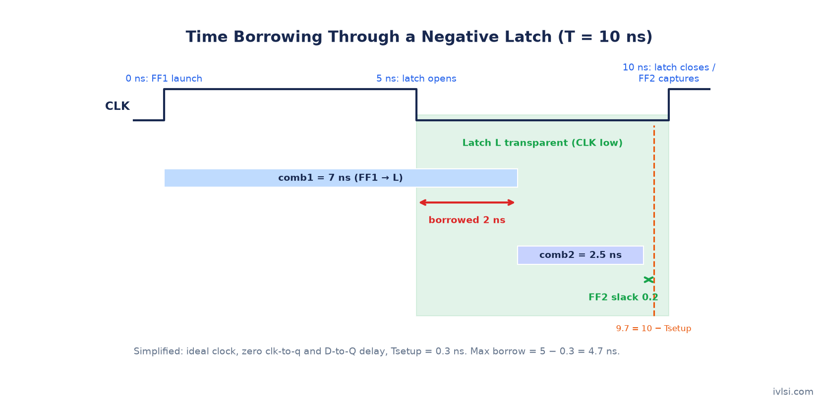
Step 1 – Latch window: L opens at the falling edge (5 ns) and closes at the next rising edge (10 ns).
Step 2 – Arrival at L: FF1 launches at 0 ns, so data arrives at L at 0 + 7 = 7 ns.
Step 3 – Borrowed time: 7 − 5 = 2 ns. Max borrow = 5 − 0.3 = 4.7 ns, so 2 ns is allowed and the latch setup check (7 ≤ 9.7) passes.
Step 4 – Next stage: the L → FF2 path starts at 7 ns (not 5 ns). Arrival at FF2 = 7 + 2.5 = 9.5 ns. Required = 10 − 0.3 = 9.7 ns. FF2 setup slack = 9.7 − 9.5 = +0.2 ns.
Step 5 – Compare with a flip-flop: if L were a negative-edge flip-flop capturing at 5 ns, comb1 would have to finish by 5 − 0.3 = 4.7 ns. With 7 ns of logic the slack would be −2.3 ns – a violation. The latch fixes it by letting comb1 use 2 ns of comb2’s half-cycle, which comb2 did not need.
What if Borrowing is Too Large?
If comb1 were 10 ns, data would reach L at 10 ns, after the 9.7 ns setup limit: latch setup slack = 9.7 − 10 = −0.3 ns. Even if it were exactly 9.7 ns, comb2 would only have 0 ns left before FF2’s required time, so FF2 would fail. The total of both stages must still fit in the overall budget:
comb1 + comb2 <= T - Tsetup(FF2)       (here 7 + 2.5 = 9.5 <= 9.7)
comb1 <= opening edge + max borrow      (here 7 <= 5 + 4.7)
This is the key insight: time borrowing does not create time. It only lets slack move from a fast stage to a slow stage across a latch.
Hold Check for Latches
For a latch, the hold check is done against the closing edge of the previous transparent window: new data launched on a clock edge must not pass through the latch while it is still holding the previous value for the next stage. In the example above, FF1 launches new data at 0 ns, and the previous window of L closed at 0 ns, so the hold requirement is simply that FF1's clock-to-Q plus comb1 minimum delay exceeds L's hold time – easy to meet.
This is why the common arrangement is alternating phases: positive-edge flops feeding negative latches (or positive latches feeding negative latches). If a positive-edge flop fed a positive latch that opens on the same edge, data launched at that edge could race straight through the open latch, creating a large hold requirement of roughly one pulse width.
| Arrangement | Setup behaviour | Hold risk |
|---|---|---|
| Pos-edge FF → negative latch → pos-edge FF | Borrowing in low phase | Low (hold checked at edge that launches data) |
| Positive latch → negative latch (two-phase) | Borrowing in each phase | Low, as long as phases do not overlap |
| Pos-edge FF → positive latch (same edge opens) | Latch opens as data launches | High: race-through, needs min delay ≈ pulse width + hold |
Where Time Borrowing is Used
- High-performance datapaths – latch-based pipelines balance uneven stages automatically.
- Integrated clock gating cells – the latch inside an ICG is a classic case of a latch timing path; see Integrated Clock Gating (ICG) Cell.
- Lockup latches in scan chains between clock domains with skew.
- Tolerance to clock skew and jitter – latch-based designs are naturally more tolerant of skew because capture is not tied to one edge.
The trade-offs are more complex STA (paths are coupled), more difficult hold analysis and tighter dependence on pulse width. Clock tree quality matters: see Clock Tree Synthesis (CTS) and Useful Skew, which is a related flip-flop based technique for shifting slack between stages.
| Technique | How slack is moved | Element |
|---|---|---|
| Time borrowing | Automatically, by late arrival in the transparent window | Latch |
| Useful skew | By deliberately delaying or advancing a clock pin | Flip-flop |
| Multicycle path | By relaxing the constraint to more than one cycle | Constraint (SDC) |
Time Borrowing Interview Questions
Q1. What is time borrowing?
The ability of a latch-based design to let a slow stage use part of the next stage's time, because data arriving during the latch's transparent window is still captured correctly.
Q2. Why can't a flip-flop borrow time?
Because it samples only at the clock edge; data arriving after the edge (minus setup) is simply too late.
Q3. What limits the maximum borrowed time?
The transparent window (pulse width) minus the latch setup time and clock uncertainty; a max borrow constraint can also limit it.
Q4. Does time borrowing increase the maximum frequency?
It can, if stages are unbalanced, because slack moves from fast stages to slow ones. It does not create time: the total delay over the stages must still fit the total budget.
Q5. How is the hold check done for a latch?
Against the closing edge of the previous transparent window, which is why alternating latch phases are used to avoid race-through.
Q6. What happens to the next path when time is borrowed?
It starts from the actual arrival at the latch D pin (through the D-to-Q arc) instead of the opening edge, so it has less time available.
Q7. What is the difference between time borrowing and useful skew?
Time borrowing happens naturally in latches; useful skew deliberately adjusts flip-flop clock latencies.
Q8. How does duty cycle affect time borrowing?
A smaller pulse width for the transparent phase reduces the maximum borrow, so duty-cycle distortion reduces margin.
FAQ
What is time borrowing in VLSI?
It is a latch timing concept in which data arriving after a latch opens (but before it closes) borrows time from the following stage, allowing unbalanced pipeline stages to meet timing.
Is cycle stealing the same as time borrowing?
Yes. Cycle stealing is another name for time borrowing.
How do you calculate the maximum time borrow?
Max borrow = closing edge − opening edge − latch setup time − clock uncertainty, i.e. the pulse width of the transparent phase minus setup and uncertainty.
Can time borrowing cause hold problems?
Not the borrowing itself, but latch-based designs need careful hold analysis, especially if a latch opens on the same edge that launches its input data.
Conclusion
Time borrowing lets latches absorb uneven logic delays by letting data arrive any time within the transparent window. Remember the three rules: borrowed time is measured from the opening edge, it cannot exceed the window minus setup, and the next stage pays for it. Continue with Setup and Hold Violations and Recovery and Removal Time to complete your timing fundamentals.